

Pressure circulation service life testing system and method
A cycle life, test system technology, applied in vibration testing, mechanical component testing, machine/structural component testing, etc., can solve the problems of inability to directly use pressure pulsation simulation test, difficult to use directly, and achieve low assembly and maintenance costs , the effect of low static load and precise pressure pulsation
Active Publication Date: 2014-04-09
TIANJIN AEROSPACE RELIA TECH
View PDF8 Cites 17 Cited by
- Summary
- Abstract
- Description
- Claims
- Application Information
AI Technical Summary
Problems solved by technology
However, the precise displacement control provided by the shaking table cannot be directly applied to the pressure pulsation simulation test
At the same time, for most of the hydraulic fatigue test equipment, the pulsation amplitude can be realized by c
Method used
View moreImage
Smart ImageViewing Examples


Examples
 PUM
 Abstract
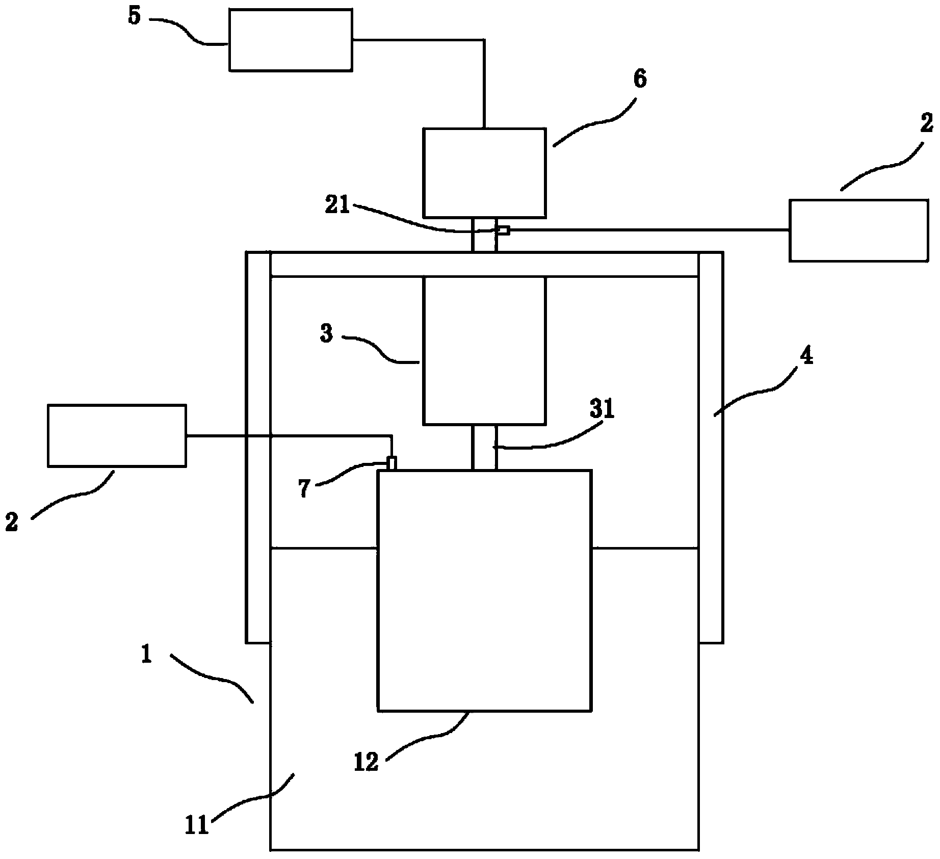
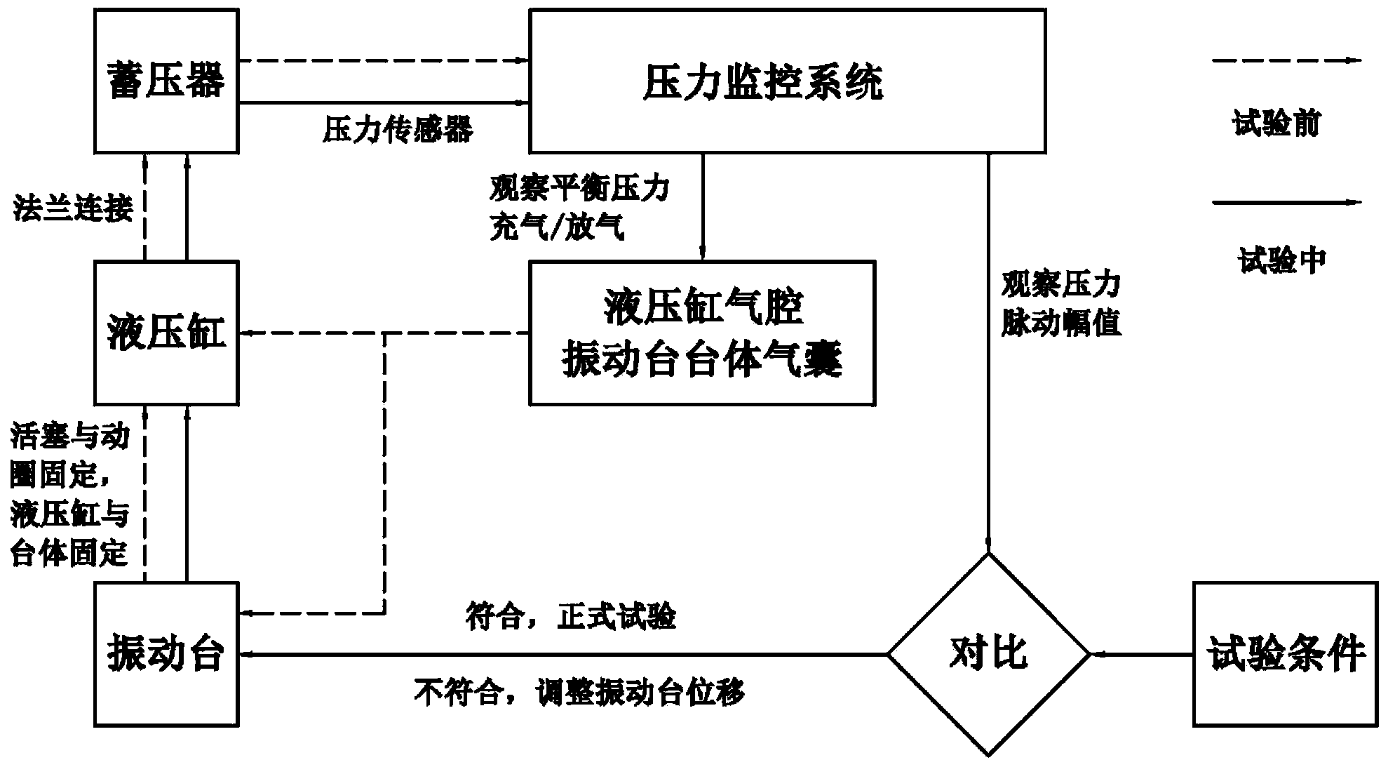
The invention discloses a pressure circulation service life testing system and method. According to the typical embodiment, a vibrating platform is provided as a power source, a hydraulic cylinder is provided as a transmission element, a piston is arranged in the hydraulic cylinder, the piston is in transmission connection with a moving component of the vibrating platform through a piston rod, air is filled into a hydraulic cylinder inner cavity located on one side, close to the vibrating platform, of the piston, a hydraulic cylinder inner cavity located on the other side of the piston is communicated with an accumulator liquid cavity, and water is filled into the hydraulic cylinder inner cavity located on the other side of the piston and into the accumulator liquid cavity. The vibrating platform is started, through motion of the moving component of the vibrating platform, water filled into the hydraulic cylinder and the accumulator liquid cavity is made to extrude an accumulator air cavity to form pressure fluctuation. The pressure circulation service life testing system can adapt to different pressure fluctuation amplitudes and frequencies conveniently by adjusting the output displacement and the frequency of the vibrating platform, so that high control precision of the pressure fluctuation is guaranteed, and the system is simple in structure, low in assembly and maintenance cost and easy to operate.
Description
technical field [0001] The invention particularly relates to a test device and method for simulating pressure fluctuations in a rocket fuel delivery pipeline for evaluating the fatigue performance of a pressure accumulator on the pipeline. Background technique [0002] The severity level of pressure pulsation in rocket fuel pipeline consists of pulsation amplitude, equilibrium pressure and pulsation frequency, and its simulated medium is usually water. At present, the electromagnetic vibrating table cooperates with the vibration controller, which can accurately realize the predetermined alternating frequency and displacement amplitude, and can also provide a large thrust. However, the precise displacement control provided by the shaking table cannot be directly applied to the pressure pulsation simulation test. At the same time, for most of the hydraulic fatigue test equipment, the pulsation amplitude can be realized by compressing the air cavity of the pressure accumulator...
Claims
Login to View More Application Information
Patent Timeline
 IPC IPC(8): G01M13/00G01M7/02
Inventor李杰徐海博
OwnerTIANJIN AEROSPACE RELIA TECH