Method and device for determining the power output by a photovoltaic installation

一种光伏设备、功率的技术,应用在光伏系统的监测、通过应用数字技术进行电功率测量、光伏模块等方向,能够解决功率剧烈变化等问题

Inactive Publication Date: 2014-04-09
SIEMENS AG
View PDF5 Cites 3 Cited by
  • Summary
  • Abstract
  • Description
  • Claims
  • Application Information

AI Technical Summary

Problems solved by technology

[0005] This is particularly problematic in the case of the mentioned renewable energies, since the supplied power can vary sharply for short periods of time

Method used


Image

  • Method and device for determining the power output by a photovoltaic installation
  • Method and device for determining the power output by a photovoltaic installation
  • Method and device for determining the power output by a photovoltaic installation

Examples


Embodiment Construction

[0059] The proposed solution for forecasting the feed-in power of a photovoltaic system (PV system) is characterized, inter alia, by being able to take into account influences due to temporary shading of the solar radiation by clouds and other climatic influences.

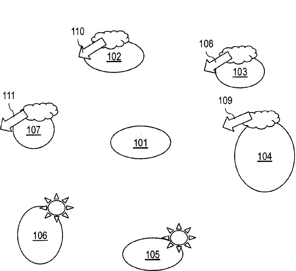
[0060] For this purpose, the information of spatially adjacent PV installations is considered in the forecast model. The use of this information can take place, for example, on the basis of a so-called measurement field, wherein the measurement field has a plurality of PV installations which spatially surround the installation currently to be observed.

[0061] figure 1 A schematic diagram is shown with one PV plant 101 and a plurality of adjacent PV plants 102-107. Each PV plant 101-107 has a measurement area by which shading can be determined. The measuring field is preferably a solar module: from the change in the output power, shading can be deduced. Thus, an individual solar module or a group of solar modul...


PUM


Abstract

The present solution improves the usability of photovoltaic installations (PV installations) by taking account of shading information of adjacent PV installations for predicting the power output by a relevant PV installation. In particular, cloud movements and cloud shapes are taken into account, thereby improving prediction accuracy. It is advantageous that short-term predictions concerning e.g. the next 15 minutes are possible and a substitute energy source can be activated accordingly in a timely manner prior to a dip in the power output by the PV installation. The invention can be used e.g. in the domain of renewable energies, PV installations or smart grids.

Description

technical field [0001] The invention relates to a method and a device for determining the power output by a photovoltaic installation. Background technique [0002] The increasing importance of renewable energies in energy networks places new demands on the prediction of the required and available feed-in power in order to thereby be able to control the network as best as possible. This challenge is reflected in the concept of the so-called "smart grid" which also allows decentralized control of the energy flow. [0003] Article Modeling of Dynamical Systems by Error Correction Neural Networks by Zimmermann H.G., Neuneier R., Grothmann R. in Modeling and Forecasting Financial Data, Techniques of Nonlinear Dynamics (Editors Soofi, A. and Cao, L., Kluwer Academic Press, 2002, pp. 237-263) the so-called Error Correction Neural Network (ECNN) is known. [0004] In order to be able to equalize the control of the load flow in the lower-level network part of the energy network wi...

Claims


Application Information

Patent Timeline
Patent Type & Authority Applications(China)
IPC IPC(8): G05F1/67H02J3/38
CPCH02J3/383Y02E10/563G01R31/405G01R21/133H02S50/10H02J2300/24H02J3/381H02J3/004Y02E10/56Y04S10/50
Inventor J·班贝格尔R·格罗特曼K·赫舍C·霍夫曼M·梅茨格
Owner SIEMENS AG
Why Eureka
Try Eureka