Pipeline joint
A technology for pipe joints and pipes, applied in the direction of pipes/pipe joints/fittings, flange connections, through components, etc., can solve the problems of difficult alignment of screw holes, reduced operator work efficiency, heavy pipeline weight, etc., to improve installation. The effect of efficiency
- Summary
- Abstract
- Description
- Claims
- Application Information
AI Technical Summary
Problems solved by technology
Method used
Image

Examples
Embodiment Construction
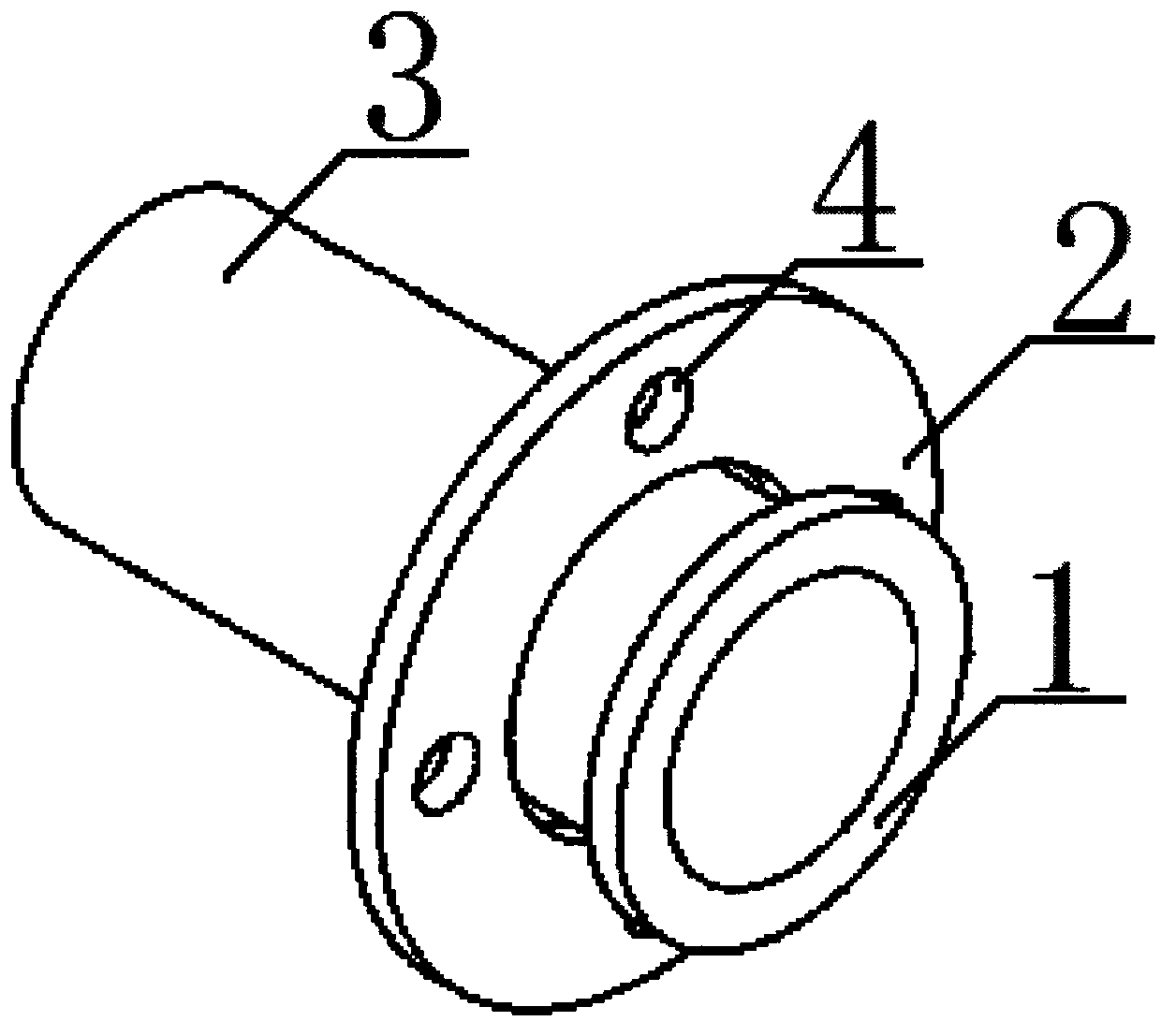
[0008] Below in conjunction with accompanying drawing, the present invention is described in further detail;
[0009] Such as figure 1 As shown, the retaining ring 1 is welded on both ends of the pipe 3, the flange 2 is set on the pipe 3, the flange 2 is movably matched with the outer wall of the pipe 3, and the flange is provided with 3-6 flange holes 4, the French The inner diameter of the flange 2 is larger than the outer diameter of the pipe 3 and smaller than the outer diameter of the retaining ring 1. During installation, two pipes 3 welded with the retaining ring 1 and fitted with the flange 2 are butted, and then the flange 2 is rotated. Align the screw holes of the flanges 2 on the two pipelines 3, and finally fasten the two flanges 2 with bolts. Because the present invention adopts the structure that the flanges are sleeved on the pipelines, the flanges can be moved along the The axis of the pipeline rotates freely, so it is very easy to quickly connect the screw ho...
PUM
 Abstract
Description
Claims
Application Information
 - Generate Ideas
- Intellectual Property
- Life Sciences
- Materials
- Tech Scout
- Unparalleled Data Quality
- Higher Quality Content
- 60% Fewer Hallucinations
Browse by: Latest US Patents, China's latest patents, Technical Efficacy Thesaurus, Application Domain, Technology Topic, Popular Technical Reports.
© 2025 PatSnap. All rights reserved.Legal|Privacy policy|Modern Slavery Act Transparency Statement|Sitemap|About US| Contact US: help@patsnap.com