A spacer bar self-locking clamp

A self-locking, spacer bar technology, applied in the direction of the device to maintain the distance between parallel conductors, can solve the problems of easy accidents, cumbersome installation, easy drop of the latch and R pin, etc., and achieve the effect of novel structure and quick installation

Active Publication Date: 2016-04-27
JIANGDONG FITTINGS EQUIP
View PDF9 Cites 0 Cited by
  • Summary
  • Abstract
  • Description
  • Claims
  • Application Information

AI Technical Summary

Problems solved by technology

There are many deficiencies in this locking method, such as: 1. Since the multi-split wires need to be repeatedly installed, for example, the four-split wires need to be installed with four pins and R pins, and the installation is cumbersome and inefficient; 2. The installation workers It is easy to forget to wear or miss the R pin, which is likely to cause accidents; 3. Due to the high-altitude operation, the plug and R pin are easy to fall during the construction process, which increases the construction cost and the incidence of accidents

Method used


Image

  • A spacer bar self-locking clamp

Examples


Embodiment Construction

[0013] In order to deepen the understanding of the present invention, the present invention will be further described below in conjunction with the embodiments and accompanying drawings. The embodiments are only used to explain the present invention and do not constitute a limitation to the protection scope of the present invention.

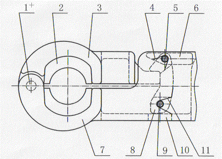
[0014] Such as figure 1 As shown, the spacer bar self-locking clamp includes a clamp body 7 and a gland 3. The front end of the clamp body 7 is hinged to the front end of the gland 3 through a hinge pin 1, and the clamp body 7 and the gland 3 are respectively A rubber tile 2 is installed, and the rubber tile 2 in the clamp body 7 cooperates with the rubber tile 2 in the gland 3 . A self-locking mechanism is also provided in the clamp body 7, which is arranged at the tail of the gland 3. The self-locking mechanism includes a locking block 8 and a base 10, and the bottom of the locking block 8 is connected by a locking shaft 9 in rotation. Inside ...


PUM


Abstract

The invention discloses a spacer self-locking cable clamp which comprises a cable clamp body and a gland. The front end of the cable clamp body is hinged to the front end of the gland through a hinge pin. Matched rubber tiles are installed in the cable clamp body and the gland respectively. The spacer self-locking cable clamp is characterized in that the tail portion, corresponding to the gland, in the cable clamp body is provided with a self-locking mechanism, the self-locking mechanism comprises a locking block and a base, and the bottom of the locking block is fixed in the cable clamp body through a locking shaft. The base is arranged below the locking block and a locking torsion spring is arranged on the locking shaft. The two ends of the locking torsion spring are in contact with the locking block and the base respectively. The top of the locking block is a hook-shaped slant face structure for the tail portion of the gland to slide downwards. The left side of the bottom of the locking block is a protruding structure which limits the locking block from swinging to the left. The right side of the bottom of the locking block is an arc structure for the locking block to swing to the right. The spacer self-locking cable clamp has the advantages that the cable clamp is novel in structure and rapid to install, insurance is automatically performed after locking and tripping will not occur.

Description

technical field [0001] The invention relates to a wire clip, in particular to a self-locking wire clip for a spacer bar. It belongs to the field of matching fittings for transmission lines. Background technique [0002] With the rapid growth of China's electricity demand, my country has accelerated the construction process of UHV transmission lines. In recent years, several ±800kV and 1000kV UHV transmission lines have been built. In the UHV transmission line, in order to increase the transmission capacity, the transmission method of multi-split conductors is adopted. In order to prevent whipping, galloping, friction, etc. between the multi-split wires, a spacer bar needs to be installed every 50 meters or so in the line, that is, the multi-split wires are respectively fixed in the clamps of the spacer bar. [0003] The traditional spacer wire clamp mostly locks the gland in the wire clamp body through the bolt after holding the wire tightly, and also inserts the R pin on ...

Claims


Application Information

Patent Timeline
Patent Type & Authority Patents(China)
IPC IPC(8): H02G7/12
Inventor 孔德春李新春徐志磊冒新国沈辉
Owner JIANGDONG FITTINGS EQUIP
Why Eureka
Try Eureka