
Electric welding machine facilitating winding of welding wires

An electric welding machine, welding machine technology, applied in welding accessories, conveying filamentous materials, thin material processing and other directions, can solve the problems of tearing, time-consuming, ground wear, etc., to meet the needs of use, reduce labor, improve safety effect

Inactive Publication Date: 2020-09-08
淮北德林机械设备有限公司
View PDF10 Cites 0 Cited by
  • Summary
  • Abstract
  • Description
  • Claims
  • Application Information

AI Technical Summary

Problems solved by technology

[0003] In the factory, a large number of welding machines are very close to each other. When performing welding work, it is difficult for workers to quickly distinguish the welding wires stacked on the ground and correspond to the welding machines one by one. Therefore, it takes a lot of time to organize the welding wires, which increases the At the same time, the welding wires stacked on the ground are extremely easy to wear on the ground or be damaged by obstacles. When not in use, it is easy to trip passers-by, which is difficult to meet the needs of use. Therefore, we propose a possible An electric welding machine that is convenient for winding the welding wire, which can be conveniently wound for the welding wire to improve the safety of the welding machine in use

Method used


Image

  • Electric welding machine facilitating winding of welding wires
  • Electric welding machine facilitating winding of welding wires
  • Electric welding machine facilitating winding of welding wires

Examples


Embodiment Construction

[0017] The following will clearly and completely describe the technical solutions in the embodiments of the present invention with reference to the accompanying drawings in the embodiments of the present invention. Obviously, the described embodiments are only some, not all, embodiments of the present invention. Based on the embodiments of the present invention, all other embodiments obtained by persons of ordinary skill in the art without making creative efforts belong to the protection scope of the present invention.

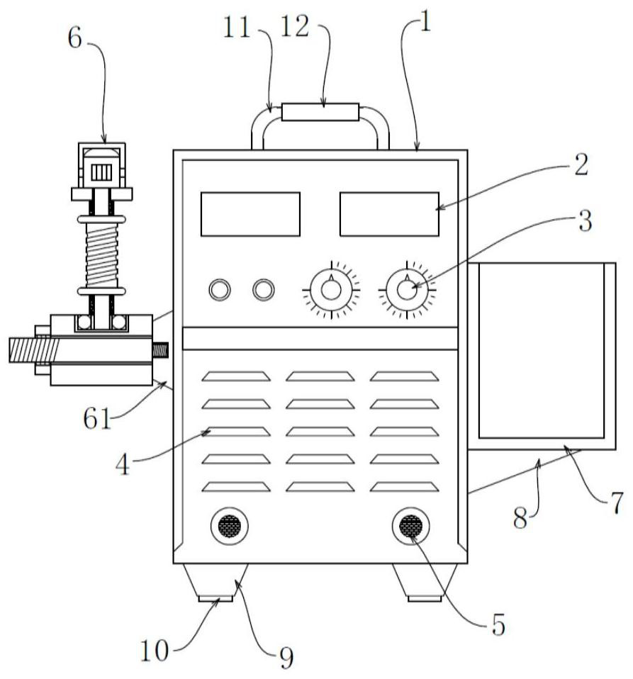
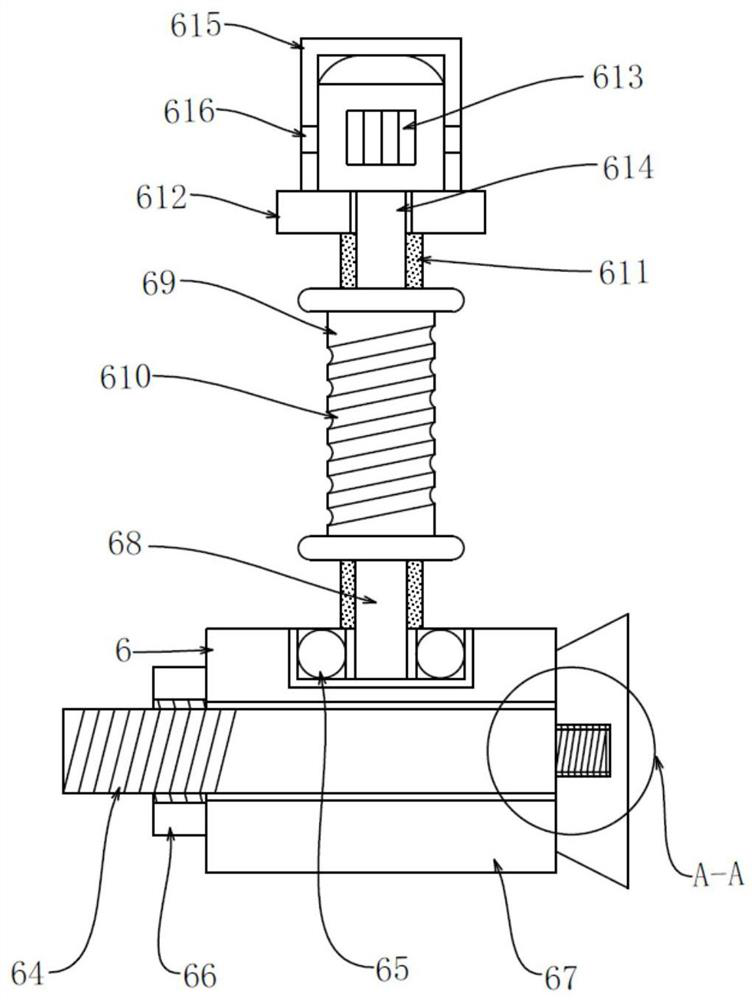
[0018] see figure 1 , the present invention provides a technical solution: an electric welding machine that can conveniently wind welding wires, including a welding machine main body 1, and the front of the welding machine main body 1 is sequentially provided with a display screen 2, an adjustment switch 3, and a heat dissipation window 4 from top to bottom And welding wire jack 5, the left side of welding machine main body 1 is fixedly connected with winding ...


PUM


Abstract

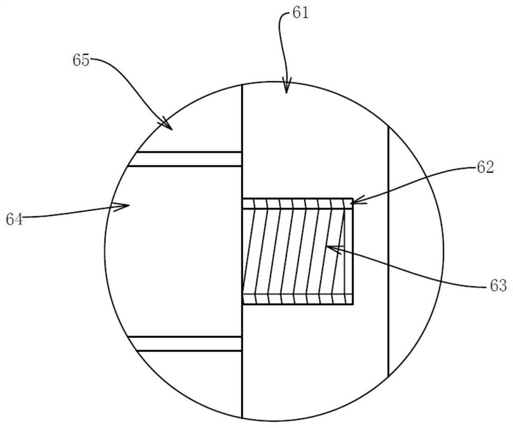
The invention discloses an electric welding machine facilitating winding of welding wires. The electric welding machine comprises a welding machine body, the front side of the welding machine body issequentially provided with display screens, adjustment switches, a heat dissipation window and welding wire insertion holes from top to bottom, and the left side of the welding machine body is fixedlyconnected with a winding device. The winding device comprises a connecting seat, the right side of the connecting seat is fixedly connected with the left side of the welding machine body, the middlepoint of the left side of the connecting seat is provided with a threaded hole, the interior of the threaded hole is in threaded connection with a threaded column, and the left end of the threaded column penetrates through the threaded hole and extends to the outside of the threaded hole to be fixedly connected with a supporting insertion rod. According to the electric welding machine, by arranging the winding device, semi-automatic winding of the welding wires is facilitated, so that the problem that as many welding wires are piled on the ground, it is difficult to distinguish the welding wires manually is solved, the labor of the workers is saved, the situation that the welding wires are worn on the ground or the wires are torn due to barriers is effectively avoided, the welding wires will not stumble passersby, the use safety is greatly improved, and use requirements can be completely met.

Description

technical field [0001] The invention relates to the technical field of welding machines, in particular to an electric welding machine which can conveniently wind welding wires. Background technique [0002] Welding machine refers to an electrical appliance that provides a certain power supply for welding. Welding is widely used in various industrial fields, such as aerospace, ships, automobiles, containers, etc. Electric welding machines are actually transformers with reduced external characteristics, which convert 220V and 380V AC into low-voltage direct current. Electric welding machines can generally be divided into two types according to the type of output power supply, one is AC power; the other is DC, DC The electric welding machine can be said to be a high-power rectifier, which is divided into positive and negative poles. When the AC power is input, it is transformed by the transformer, then rectified by the rectifier, and then outputs a power supply with reduced ext...

Claims


Application Information

Patent Timeline
Patent Type & Authority Applications(China)
IPC IPC(8): B23K9/32B65H54/48B65H54/74
CPCB23K9/32B65H54/48B65H54/74B65H2701/34
Inventor 耿洪玲
Owner 淮北德林机械设备有限公司
Learn More