Electrothermal film and heating structure

An electric heating film and heating layer technology, applied in electric heating devices, ohmic resistance heating, electrical components, etc., can solve problems such as short circuits and safety hazards, and achieve the effect of reducing the risk of current leakage and large contact resistance.

Active Publication Date: 2021-11-12
SUZHOU HANANO MATERIALS TECH LTD
View PDF10 Cites 0 Cited by
  • Summary
  • Abstract
  • Description
  • Claims
  • Application Information

AI Technical Summary

Problems solved by technology

[0003] see figure 1 , in the existing actual construction, the traditional electrothermal film with shielding layer is perforated (destroying the hole or destroying the structure such as figure 1 Mark 6 in ) after electrification, the heating layer 1 and shielding layer 2 of the electrothermal film will be partially short-circuited and ignited. As a result, the continuous combustion phenomenon of the electrothermal film occurs; and, since the structure of the electrothermal film is usually composed of a polymer film such as PET and a heat-generating layer, it is difficult for this structure not to be pierced by nails or sharp stones. The shielding layer with almost the same area of ​​the heating layer is very easy to form a local short circuit with the heating layer (the shielding layer is the neutral line, and the circuit voltage division of the heating layer is 0V~220V), especially the perforated part with a large voltage difference (120V~220V) will Sparking occurs, and the resulting high temperature further causes the polymer films such as PET in the electrothermal film structure to burn, causing huge safety hazards

Method used


Image

  • Electrothermal film and heating structure
  • Electrothermal film and heating structure
  • Electrothermal film and heating structure

Examples


Embodiment 1

[0062] The process of laying the electric heating film by the electric heating film wet method includes:

[0063] Provides a power density of 230W / m 2 The carbon nanotube heating film is used as the heating film;

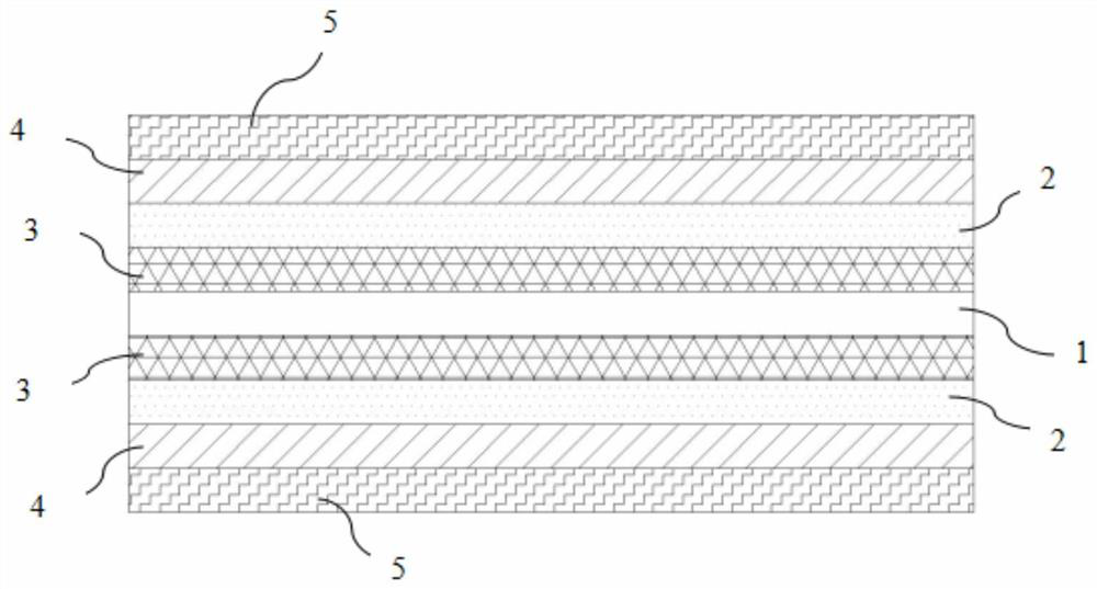
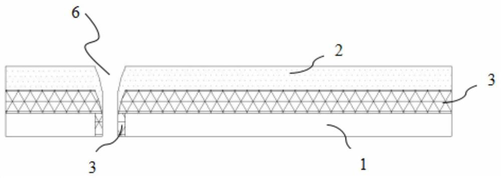
[0064] Lay glass fiber cloth layers with a thickness of 0.2mm on the opposite sides of the heating film as a fireproof insulation layer;

[0065] Lay aluminum foil with a thickness of 7 μm on the side of the glass fiber cloth away from the heating film as a shielding layer (the square resistance is 0.02Ω / sq), and the area ratio of the heating film to the shielding layer is 1:0.83;

[0066] Lay a polyester film with a thickness of 0.025mm on the side of the shielding layer away from the fireproof insulation layer as the insulating layer;

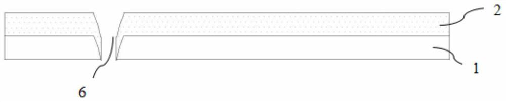
[0067] A polyvinyl chloride film bag with a thickness of 0.6mm is packaged on the outer surface of the insulating layer as a protective layer, and the final electric heating film structure is as follows: figure 2 shown.

[006...

Embodiment 2

[0070] The process of laying the electric heating film by the electric heating film wet method includes:

[0071] The power density is 230W / m 2 The carbon nanotube heating film is used as the heating film;

[0072] Lay basalt fiber cloth with a thickness of 0.2mm on the opposite sides of the heating film as a fireproof insulation layer;

[0073] Lay aluminum foil with a thickness of 7 μm on the side of the glass fiber cloth away from the heating film as a shielding layer (the square resistance is 0.02Ω / sq), and the area ratio of the heating film to the shielding layer is 1:0.83;

[0074] Lay a polyester film with a thickness of 0.025mm on the side of the shielding layer away from the fireproof insulation layer as the insulating layer;

[0075] A polyvinyl chloride film bag with a thickness of 0.6mm is packaged on the outer surface of the insulating layer away from the shielding layer as a protective layer, and the formed electric heating film structure is as follows: figur...


PUM

PropertyMeasurementUnit
thicknessaaaaaaaaaa
thicknessaaaaaaaaaa
thicknessaaaaaaaaaa

Abstract

The invention discloses an electric heating film and a heating structure. The electrothermal film includes a heating layer, at least one side of the heating layer is closely attached to a fireproof insulation layer, and a shielding layer is stacked on the fireproofing insulation layer, and the shielding layer is electrically connected to the neutral terminal of the heating layer. connection, the heating layer is also provided with live wire terminals. Even if the electrothermal film provided by the embodiment of the present invention is damaged by puncture or the like during construction, it can still be used normally; due to the existence of the fireproof insulation layer, it can ensure that the local structure damaged by perforation will not be further expanded due to burning or ignition. Therefore, the risk of current leakage can be greatly reduced, and the leakage protection device of the entire circuit will not be tripped; at the same time, the electric heating film provided by the embodiment of the present invention has a relatively large contact resistance due to the carbon-based heating layer, so there is almost no risk of contact electric shock, and it is safe to use high sex.

Description

technical field [0001] The invention relates to an electric heating film structure, in particular to an electric heating film and a heating structure, and belongs to the technical field of electric heating film. Background technique [0002] With the improvement of people's living standards and the advancement of science and technology, electrothermal film, as a new star in the field of floor heating and heating, is more and more popular because of its large heating area, energy saving and environmental protection, rapid heating, high conversion efficiency of far infrared rays, and the function of physical therapy and health care. favored by more and more consumers. However, in the actual laying process, especially when the cement mortar is covered above the electrothermal film, due to the formation of distributed capacitance between the planar heating electrothermal film and the cement mortar layer, it is easy to cause the leakage current of the distributed capacitance; Th...

Claims


Application Information

Patent Timeline
Patent Type & Authority Patents(China)
IPC IPC(8): H05B3/14H05B3/36
CPCH05B3/14H05B3/36
Inventor 陈新江李峰周红波沈珍辉
Owner SUZHOU HANANO MATERIALS TECH LTD
Why Eureka
Try Eureka