
Horizontal compensation mechanism used for dental chair

A compensation mechanism, a technology for dental chairs, applied in dental chairs, dental chairs, surgical chairs, etc., can solve the problems of backrest and seat cushion rubbing, occupying a large space, unsatisfactory, etc., and achieve the effect of stable transmission and low resonance sound.

Inactive Publication Date: 2014-04-23
SINOL MEDICAL EQUIP GRP CO LTD
View PDF3 Cites 5 Cited by
  • Summary
  • Abstract
  • Description
  • Claims
  • Application Information

AI Technical Summary

Problems solved by technology

[0002] Most of the existing dental chair backrest pitching and rotating mechanisms adopt a structure in which a curved plate rotates along a fixed fulcrum. This type of dental chair structure takes up a relatively large space, and at the same time, the position of the rotating fulcrum is relatively high during use, causing the patient to sit uncomfortable. In addition, the seat cushion of the backrest will be severely rubbed during the movement process, and the seat cushion is also easily damaged; some backrest pitching mechanisms are designed with guide rails in the dental chair. With this transmission mode, there is no horizontal compensation effect during the backrest movement process. , is also unsatisfactory, so it is necessary to improve

Method used


Image

  • Horizontal compensation mechanism used for dental chair
  • Horizontal compensation mechanism used for dental chair
  • Horizontal compensation mechanism used for dental chair

Examples


Embodiment Construction

[0012] Attached below Figure 1-5 An embodiment of the present invention is described.

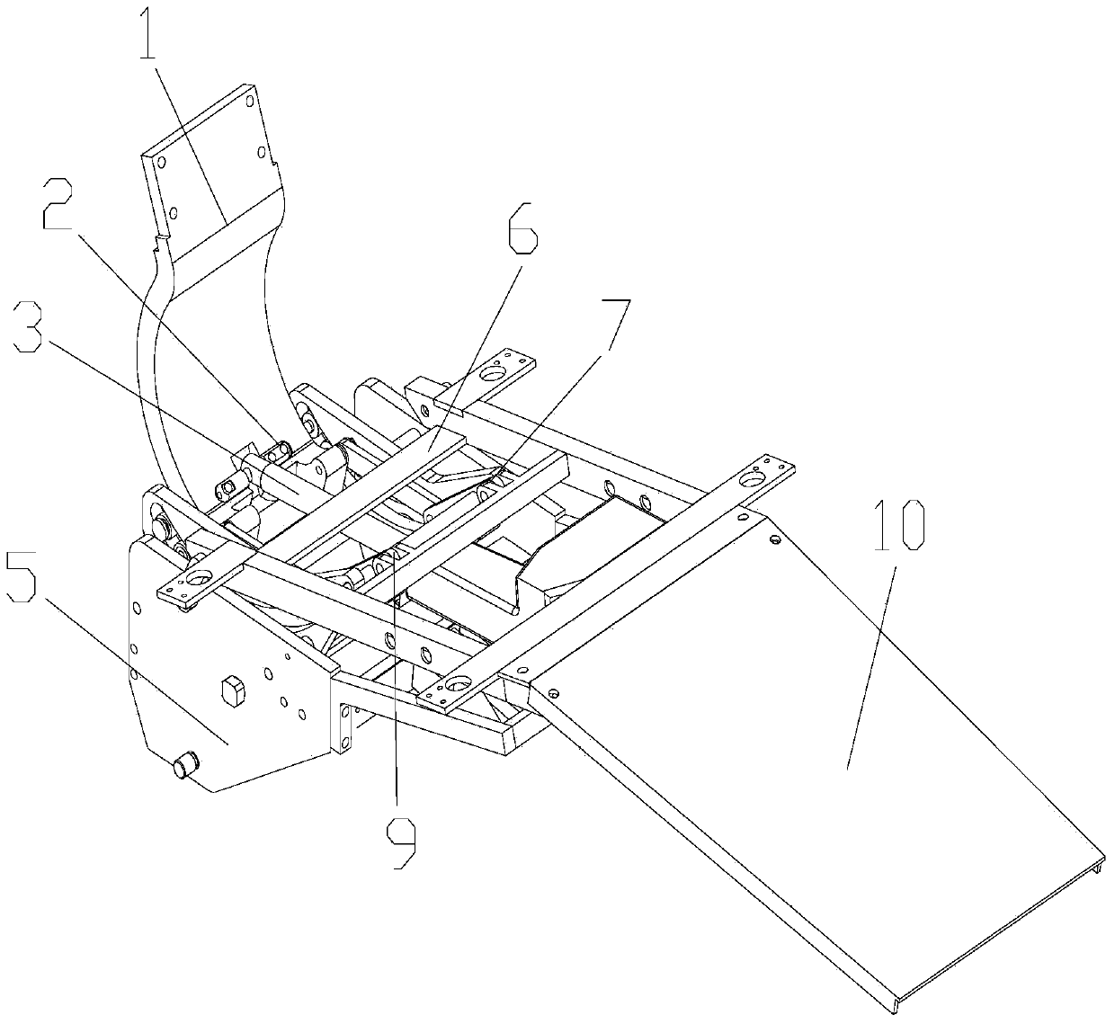
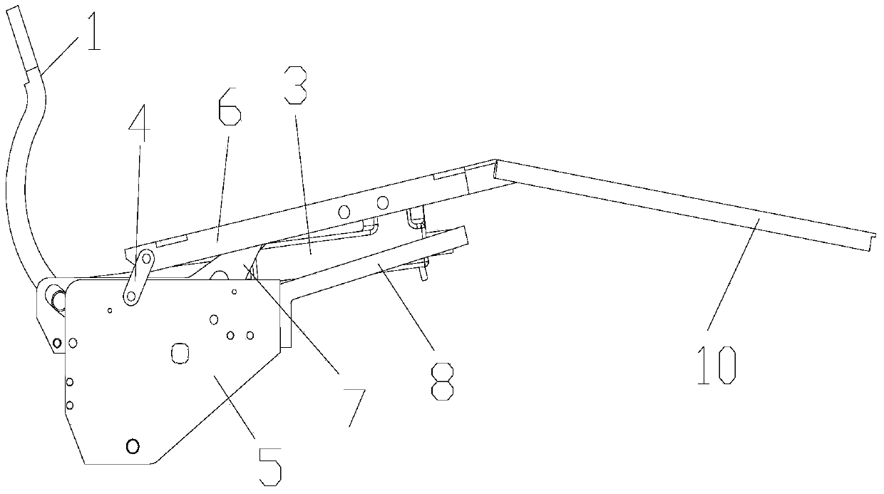
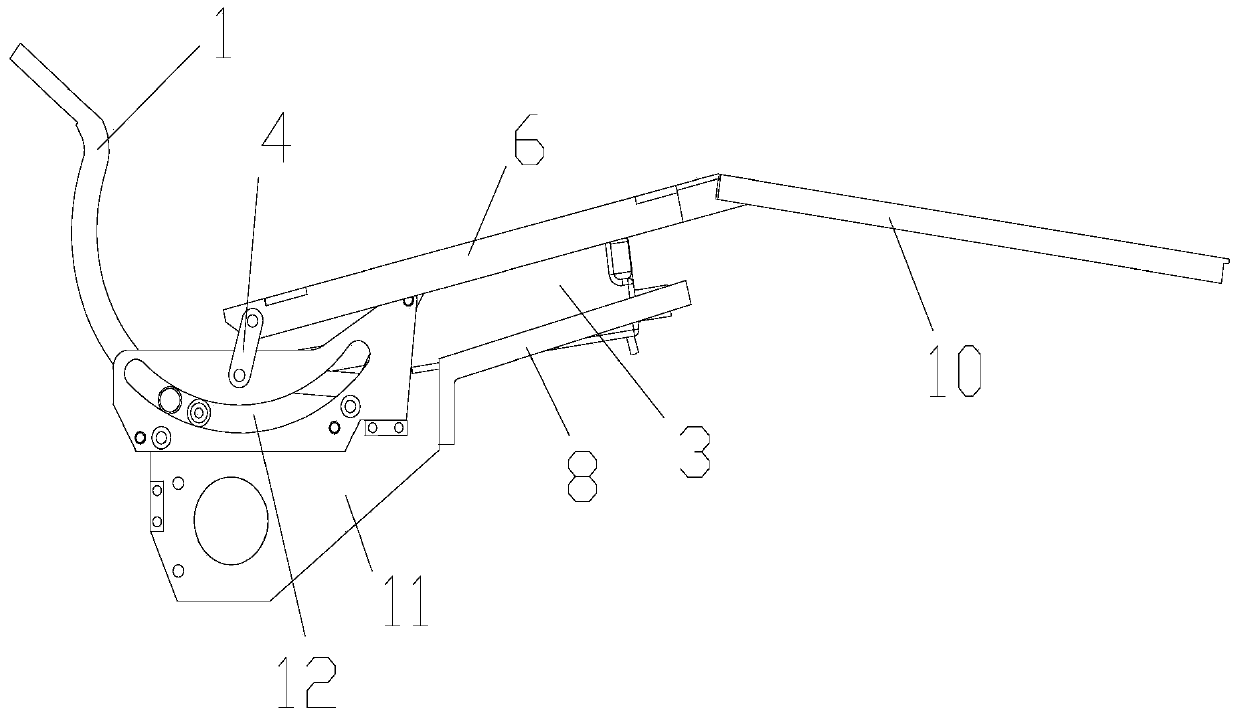
[0013] A horizontal compensation mechanism for a dental chair, which has a curved plate 1, a DC motor 3, a seat cushion support 6, an extension plate 10, a left side plate 5 and a right side plate 11, and the left side plate 5 and the right side plate 11 There are guide rails 7 between them, and the guide rails 7 are formed with arc-shaped grooves 12 matching the shape of the bent plate 1. Specifically, the two ends of the guide rails 7 are fixed between the left side plate 5 and the right side plate 11, and the arc-shaped The arc portion of the groove 12 is provided with a screw that prevents the bent plate 1 from coming out during reciprocating motion, so that the bent plate 1 can slide through the guide rail arc groove 12, but cannot swing left and right. The upper end of the curved plate 1 fixes the back support plate, the lower end of the curved plate 1 passes through the arc groove ...


PUM


Abstract

The invention provides a horizontal compensation mechanism used for a dental chair. A guide rail is arranged between a left side plate and a right side plate and is provided with an arc-shaped groove matching with the shape of a bend board, the lower end of the bend board penetrates the arc-shaped groove and is connected with one end of a driving connecting rod, the other end of the driving connecting rod is connected with a seat cushion support arranged above the left side plate and the right side plate, one end of the seat cushion support is fixedly connected with an extending plate, two side portions of the other end of the seat cushion support are respectively connected with the left side plate and the right side plate via a driven connecting rod, motor support plates for supporting direct current motors are arranged on the end portions of the left side plate and the right side plate, and a motor shaft of the direct current motor and the inner side of the bend board are connected with each other to drive the bend board to move back and forth along the arc-shaped groove to enable the driving connecting rod to drive the seat cushion support and the extending plate to move horizontally and up and down at the same time. The horizontal compensation mechanism is stable in transmission, and small in resonance voice generation, and can ensure the seat cushion support to move horizontally and up and down during back pitching process, no back rubbing and body pressing condition happen, and patients feel comfortable on seat.

Description

technical field [0001] The invention relates to a horizontal compensation mechanism for a dental chair. Background technique [0002] Most of the existing dental chair backrest pitching and rotating mechanisms adopt a structure in which a curved plate rotates along a fixed fulcrum. This type of dental chair structure takes up a relatively large space, and at the same time, the position of the rotating fulcrum is relatively high during use, causing the patient to sit uncomfortable. In addition, the seat cushion of the backrest will be severely rubbed during the movement process, and the seat cushion is also easily damaged; some backrest pitching mechanisms are designed with guide rails in the dental chair. With this transmission mode, there is no horizontal compensation effect during the backrest movement process. , is also unsatisfactory, so it is necessary to improve it. Contents of the invention [0003] The technical problem solved by the present invention is to provid...

Claims


Application Information

Patent Timeline
Patent Type & Authority Applications(China)
IPC IPC(8): A61G15/10
Inventor 李爱国唐剑王仓库何鹏聂西社
Owner SINOL MEDICAL EQUIP GRP CO LTD
Learn More