Human-like biped robot foot structure

A biped robot and foot technology, applied in the field of robotics, can solve problems such as the influence of robot gait stability, the limitation of robot foot joint freedom, and the lack of normal functions of human feet, so as to improve walking stability and improve walking Good stability and shock absorption effect

Inactive Publication Date: 2014-04-23
TIANJIN UNIVERSITY OF SCIENCE AND TECHNOLOGY
View PDF9 Cites 51 Cited by
  • Summary
  • Abstract
  • Description
  • Claims
  • Application Information

AI Technical Summary

Benefits of technology

Foot structures are developed that overcome problems associated with current robotic legs such as instability during stance phases or poor balance control caused by their rigidity. These feet have multiple degrees of movement called multiflexions (MF) allowing them to walk smoothly on uneven surfaces like rocks or snow covered ground without losing contact altogether. They use special materials made from biological material to absorb energy when they hit an object while still being able to move freely around it effectively. Additionally, these designs include soft metal plates attached at different points along its length to reduce friction between parts. Overall, this technology allows for better performance and safety compared to traditional methods used nowadays.

Problems solved by technology

This patented technical problem addressed in this patents relates to improving the performance and functionality of humanoids (humane) bipeds without sacrificing mobility capabilities like legs. Humans tend towards having unique movements such as running down stairs while they walk around indoors due to lack of muscle strength compared to machines. To address these issues, we developed a new type called the compound leg prosthetic device described earlier in previous works.

Method used


Image

  • Human-like biped robot foot structure
  • Human-like biped robot foot structure
  • Human-like biped robot foot structure

Examples


Embodiment Construction

[0023] The present invention will be further described in detail below through the specific examples, the following examples are only descriptive, not restrictive, and cannot limit the protection scope of the present invention with this.

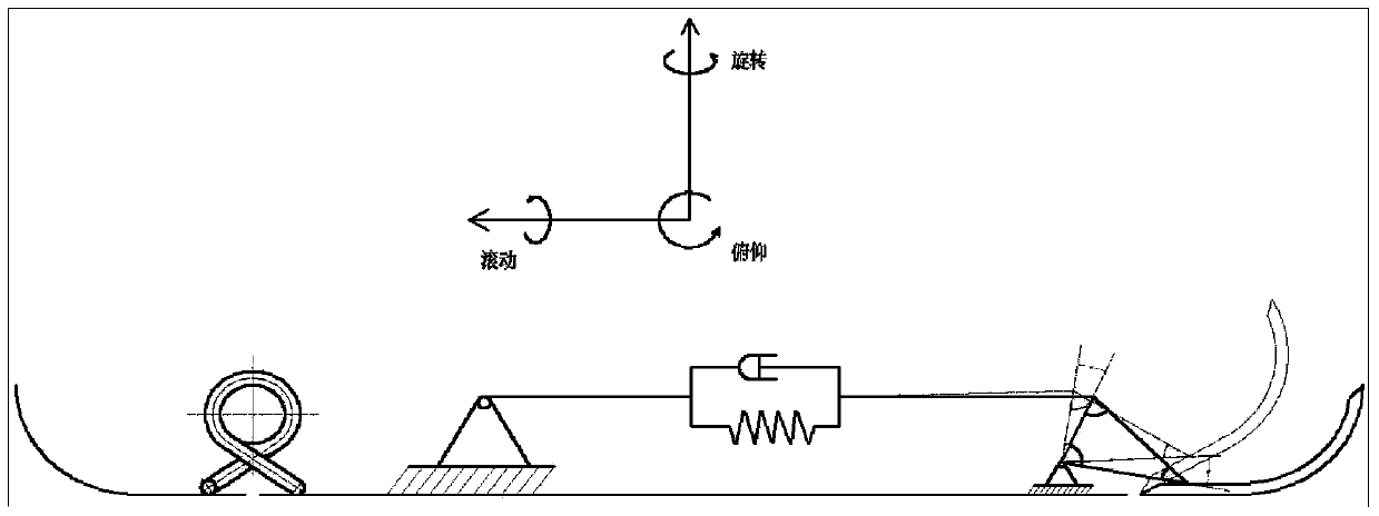
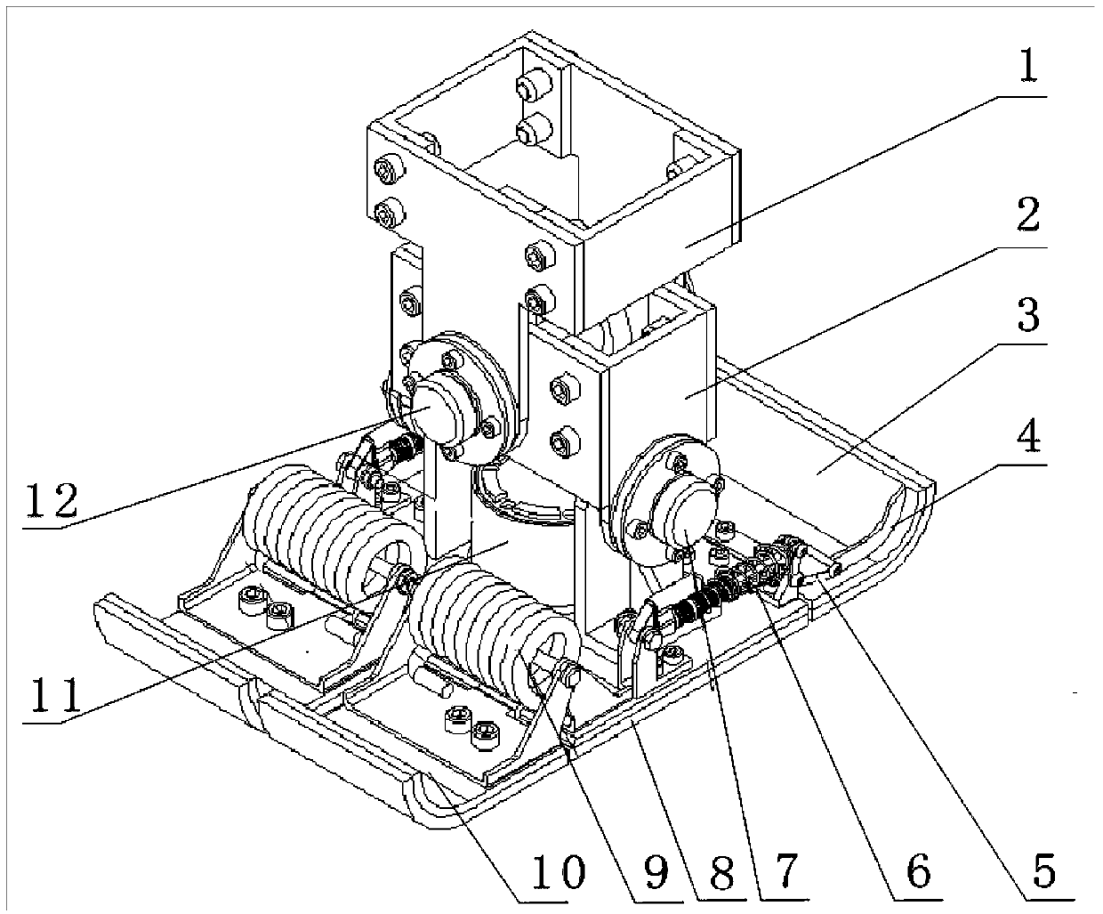
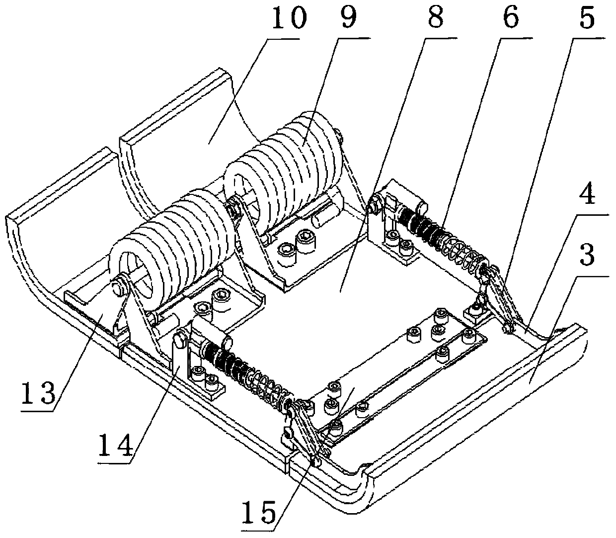
[0024] A humanoid biped robot foot structure, including sole 8, metatarsophalangeal joint 10, heel 3 and ankle joint assembly, the accompanying drawing of this embodiment shows a single robot foot structure, take this embodiment as an example To illustrate, the metatarsophalangeal joint is installed on the front end of the sole, the heel is installed on the rear end of the sole, and the ankle joint assembly is installed on the upper end of the sole of the foot. The specific installation structures are as follows:

[0025] The upper end of the middle part of the sole is fixed with an ankle joint assembly, and the ankle joint assembly includes an ankle joint holder 16, a transverse axis 7, a lower ankle joint 2, a longitudinal axis 12 and an up...


PUM


Abstract

The invention relates to a human-like biped robot foot structure which comprises a sole, metatarsophalangeal joints, a heel and an ankle joint assembly. The metatarsophalangeal joints are installed at the front end of the sole, the heel is installed at the rear end of the sole, the ankle joint assembly is installed at the upper end of the middle of the sole, and the ankle joint assembly is fixedly installed at the upper end of the middle portion of the sole. The two metatarsophalangeal joints are symmetrically hinged to the vertical front end of the sole, an upwarping arc structure is manufactured at the front end of each metatarsophalangeal joint, and a torsion spring is installed between each metatarsophalangeal joint and the sole through a torsion spring support. The heel is coaxially hinged to the rear end of the sole in the vertical direction, an upwarping arc structure is manufactured at the rear end of the heel, a pair of reinforcing ribs is symmetrically and fixedly installed on each side of the upper end of the heel, and a damper is installed between each side of the heel and the sole. The structure utilizes the compression and stretching functions of the torsion springs to achieve high flexion and extension degree of freedom of the metatarsophalangeal joints, is good in damping effect, stable and reliable in operation and capable of being perfectly matched with most available robots and improves robot walking stability.

Description


Claims


Application Information

Patent Timeline
Owner TIANJIN UNIVERSITY OF SCIENCE AND TECHNOLOGY
Why Eureka
Try Eureka