
A multi-axis linkage device

A technology of multi-axis linkage and rotating pair, which is applied in the direction of feeding devices, large fixed members, metal processing machinery parts, etc., can solve the problems of mechanical interference stiffness, complex kinematic structure of five branch chains, etc., and achieve the effect of large rotation output capacity

Active Publication Date: 2018-04-10
TSINGHUA UNIV
View PDF8 Cites 0 Cited by
  • Summary
  • Abstract
  • Description
  • Claims
  • Application Information

AI Technical Summary

Problems solved by technology

[0004] While Metrom has achieved the above success, there are still some key technical problems to be solved, such as the kinematics and structural complexity brought about by the five-branched chain, which in turn leads to mechanical interference and stiffness.

Method used


Image

  • A multi-axis linkage device
  • A multi-axis linkage device
  • A multi-axis linkage device

Examples


Embodiment 1

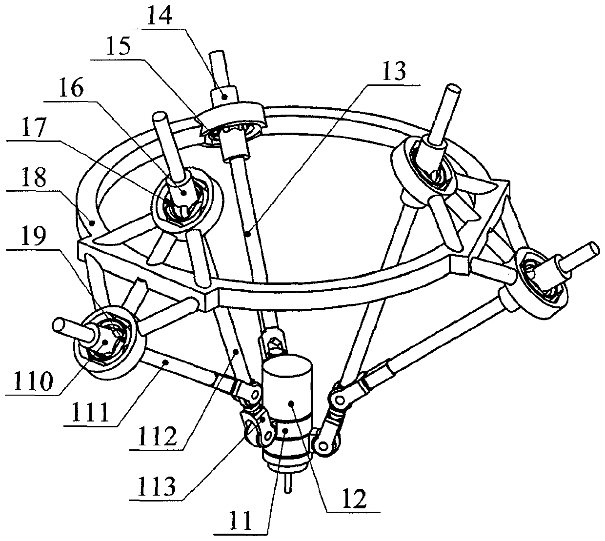
[0024] The structure of a novel multi-axis linkage device in this embodiment is as follows: figure 1 Shown, comprise fixed platform 18, moving platform 12 and first, second, the 3rd branch chain, described three branch chains are connected between fixed platform 18 and moving platform 12 respectively, and with this fixed platform 18, and moving platform The platform 12 constitutes a space closed-loop mechanism.

[0025] The first and second branch chains all include: an upper connecting piece 17, a lower connecting piece 19, an upper slider 16, a fast slide 110, an upper connecting rod 112, a lower connecting rod 111, a U-shaped piece 113, a connecting block 11 and sports vice. There are ten kinematic pairs, one is a rotating pair connected between the fixed platform 18 and the lower connecting piece 19, one is a rotating pair connected between the lower connecting piece 19 and the lower slider 110, and one is connected to the lower connecting piece 19. The moving pair betwe...

Embodiment 2

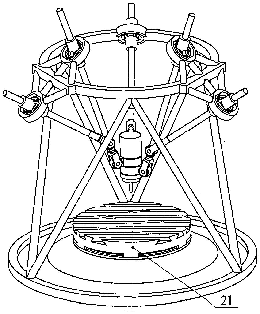
[0029] The structure of a novel multi-axis linkage device in this embodiment is as follows: figure 2 As shown, the multi-axis linkage device is different from Embodiment 1 in that: the multi-axis linkage device also includes a turntable 21 and a kinematic pair. There is one kinematic pair, which is a rotary pair connected between the fixed platform 18 and the turntable 21, and the rotary pair is driven. The device can realize six-axis linkage control of four rotation degrees of freedom and two movement degrees of freedom.

Embodiment 3

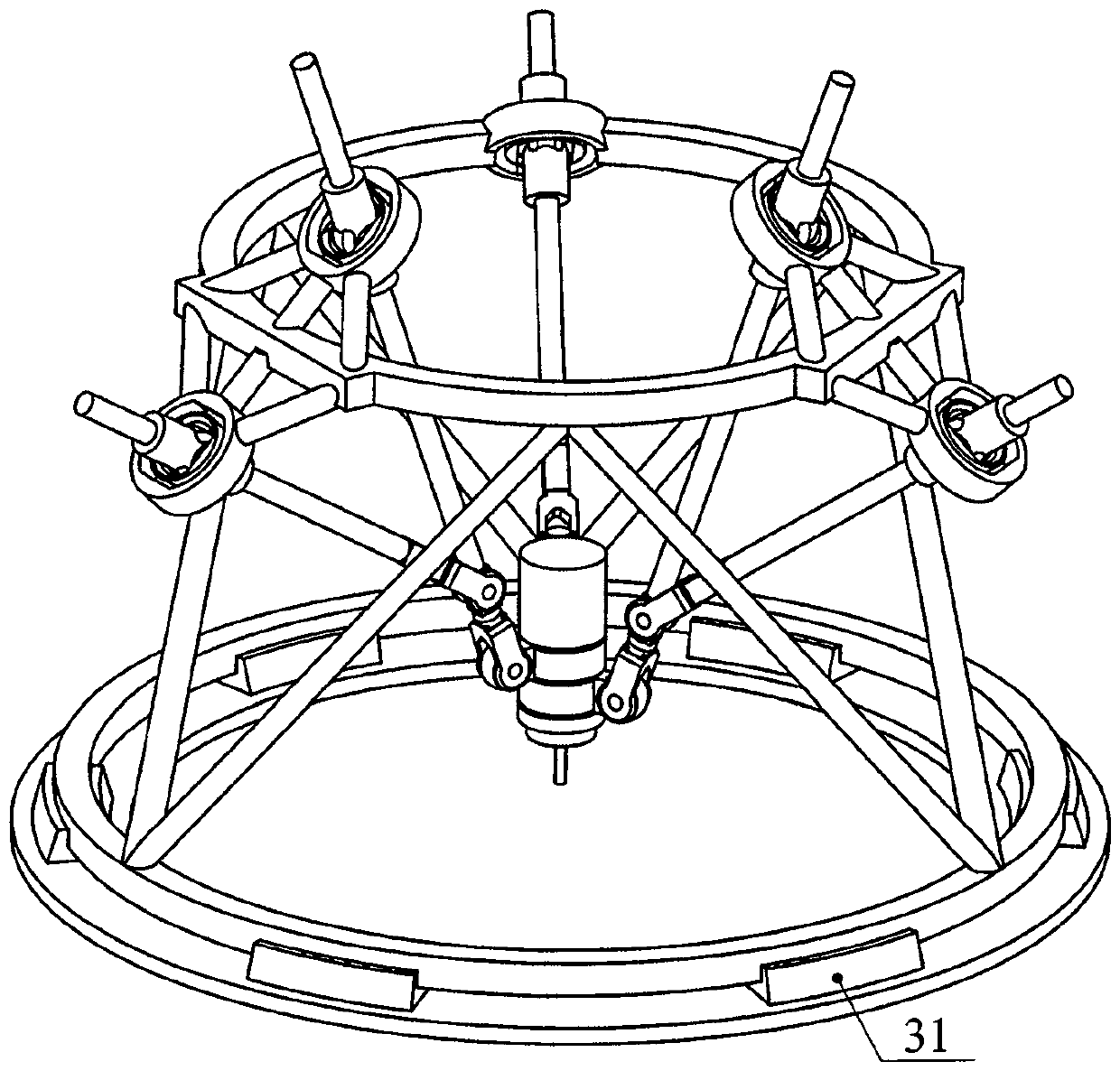
[0031] The structure of a novel multi-axis linkage device in this embodiment is as follows: image 3 As shown, the multi-axis linkage device is different from Embodiment 1 in that: the multi-axis linkage device also includes a ring guide rail 31 and a kinematic pair. The kinematic pair has one, which is a rotary pair connected between the fixed platform 18 and the annular guide rail 31, and the rotary pair is driven. The device can realize six-axis linkage control of four rotation degrees of freedom and two movement degrees of freedom.


PUM


Abstract

The invention belongs to the technical field of numerical control equipment manufacture, and relates to a novel multi-axis linkage hybrid device comprising a moving platform and a fixed platform which are used for mounting an executer and a third branch chain connecting the moving platform and the fixed platform. The third branch chain comprises a kinematic pair which drives actively. The novel multi-axis linkage device is characterized by further comprising a first and second branch chains, in the same structures, which connects between the moving platform and the fixed platform; the first and second branch chains both comprise two kinematic pairs which drive actively; the first, second and third branch chain are respectively connected to the moving platform and the fixed platform to form a spatial parallel loop mechanism, the moving platform are driven through five input motions to move, and three moving and two rotating degrees of freedom are achieved; the device further comprises an annular guide rail or workbench, and the spatial parallel loop mechanism and the annular guide rail or workbench form a hybrid device capable of realizing six-axis linkage. The output motion with five degrees of freedom can be realized through the three branch chain structure, structure is compact, and kinematics is simple.

Description

technical field [0001] The invention belongs to the field of mechanical manufacturing, and in particular relates to a novel movable and portable multi-axis linkage device which can be applied to the field of numerical control device manufacturing. Background technique [0002] In the field of machinery manufacturing, with the design of modern parts becoming more and more advanced and the processing technology more and more complex, large space free-form surface parts have been widely used in various key fields, such as aerospace, automobiles, marine propellers, turbines, etc. leaves etc. Such applications require manufacturing and processing equipment to be able to realize five-axis linkage processing capabilities, and under harsh working conditions, processing equipment is required to be able to realize five-sided processing with one clamping. In short, modern processing equipment should have better processing flexibility, rotation flexibility and higher processing efficie...

Claims


Application Information

Patent Timeline
Patent Type & Authority Patents(China)
IPC IPC(8): B23Q1/64
CPCB23Q1/64B23Q5/22
Inventor 谢福贵刘辛军汪劲松
Owner TSINGHUA UNIV
Learn More