A rail-type large-span foldable processing robot
A large-span, orbital technology, applied in manipulators, manufacturing tools, program-controlled manipulators, etc., can solve the problems of error accumulation and large inertia of moving parts, and achieve the effect of large rotational output capacity and high normal stiffness.
- Summary
- Abstract
- Description
- Claims
- Application Information
AI Technical Summary
Problems solved by technology
Method used
Image
Examples
Embodiment 1
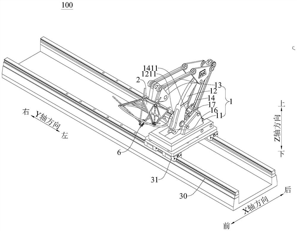
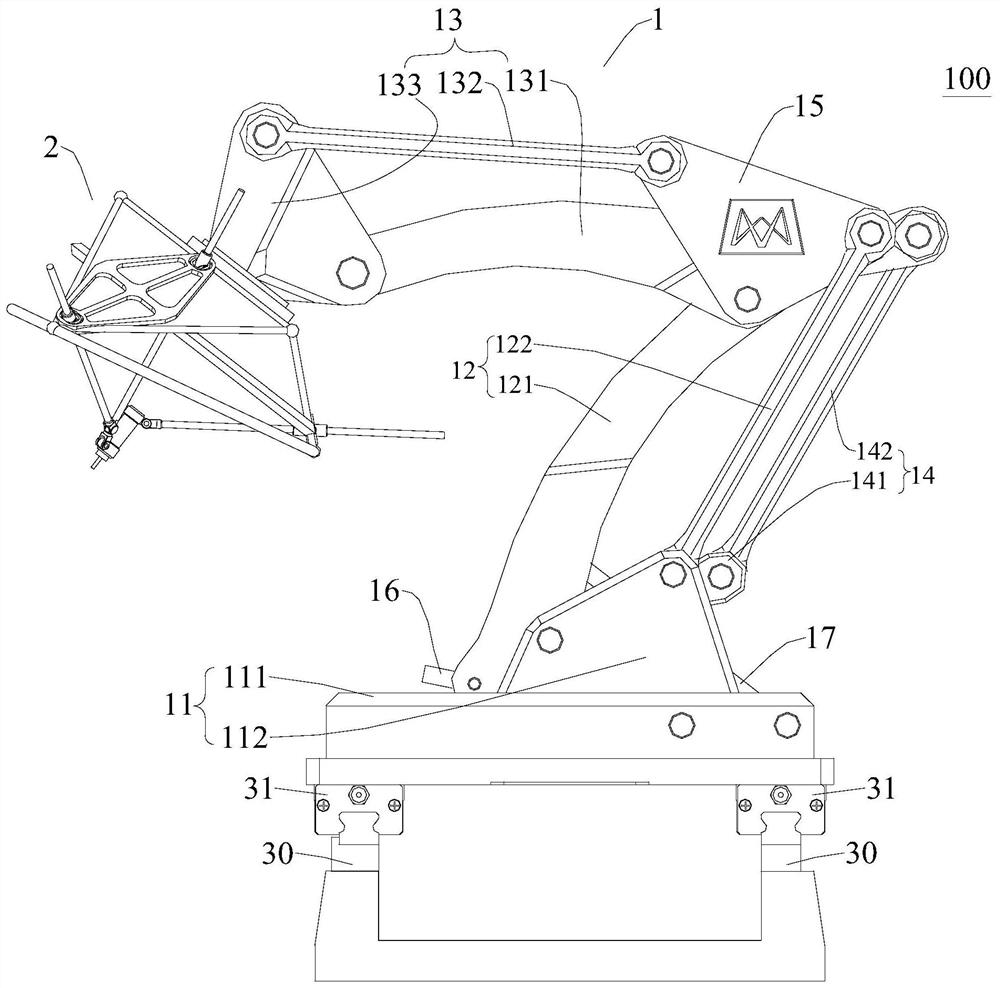
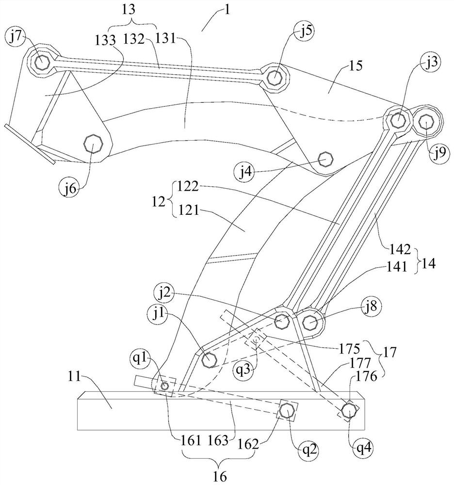
[0089] Figure 1-Figure 4 Shown is the rail-type large-span foldable processing robot 100 of the first embodiment.
[0090] In the first embodiment, the track-type large-span foldable processing robot 100 includes: a five-degree-of-freedom terminal attitude adjustment device 2 and a two-degree-of-freedom foldable mechanism 1 .
[0091] The two-degree-of-freedom expandable mechanism 1 includes: a base 11 , a first-level parallelogram structure 12 , a second-level parallelogram structure 13 , a middle triangular plate 15 , a first drive assembly 16 and a second drive assembly 17 .
[0092] The base 11 includes a base plate 111 and a boss 112, the base plate 111 is horizontally arranged, and the boss 112 is provided with a first hinge point j1 and a second hinge point j2 spaced apart, the first hinge point j1 is in front, and the second hinge point j2 is in the front Later, and the second hinge point j2 is higher than the first hinge point j1. Specifically, the bottom plate 111...
Embodiment 2
[0112] Figure 5-Figure 8 Shown is the rail-type large-span foldable processing robot 100 of the second embodiment.
[0113] In the second embodiment, the structure of the rail-type large-span foldable processing robot 100 is basically the same as that of the first embodiment, and the same parts will not be repeated.
[0114] The difference is that in the second embodiment, as Figure 5-Figure 8 As shown, the position of the first driving assembly 16 is different from that of the first embodiment. For convenience, refer to the attached Figure 7 To understand this solution, the rotational connection point of the first top block 161 on the first connecting rod 121 is called k1, and the rotational connection point of the first support block 162 on the base 11 is the second hinge point j2, image 3 The three points j1, j2, and k1 identified in are in a triangular distribution, and k1 is located between j1 and j4. When the first drive rod 163 expands and contracts relative to ...
PUM
 Abstract
Description
Claims
Application Information
 - R&D
- Intellectual Property
- Life Sciences
- Materials
- Tech Scout
- Unparalleled Data Quality
- Higher Quality Content
- 60% Fewer Hallucinations
Browse by: Latest US Patents, China's latest patents, Technical Efficacy Thesaurus, Application Domain, Technology Topic, Popular Technical Reports.
© 2025 PatSnap. All rights reserved.Legal|Privacy policy|Modern Slavery Act Transparency Statement|Sitemap|About US| Contact US: help@patsnap.com


