
Multi-axis linkage based on modules in parallel

A multi-axis linkage and parallel technology, which is used in feeding devices, large fixed members, metal processing machinery parts, etc., can solve the problem of inability to achieve vertical and horizontal conversion, and achieve the effect of large rotation output capacity.

Active Publication Date: 2014-04-30
TSINGHUA UNIV
View PDF5 Cites 9 Cited by
  • Summary
  • Abstract
  • Description
  • Claims
  • Application Information

AI Technical Summary

Problems solved by technology

Left and right, unable to achieve vertical and horizontal conversion

Method used


Image

  • Multi-axis linkage based on modules in parallel
  • Multi-axis linkage based on modules in parallel
  • Multi-axis linkage based on modules in parallel

Examples


Embodiment 1

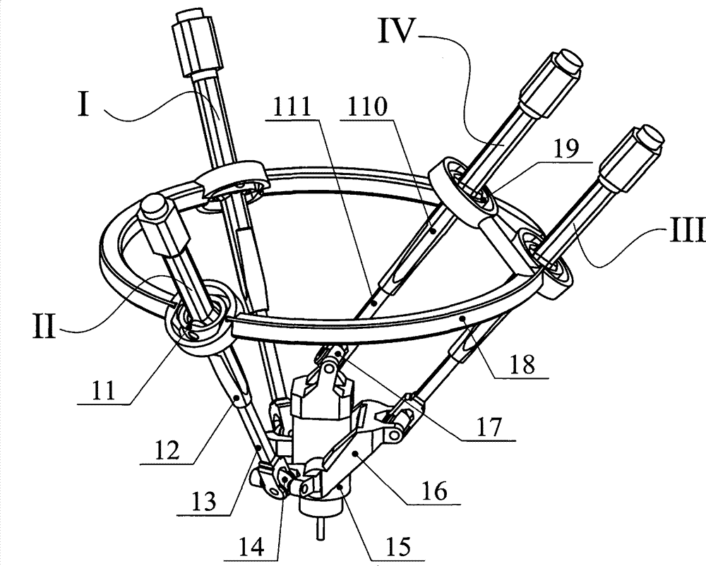
[0020] The structure of a multi-axis linkage device based on parallel modules in this embodiment is as follows figure 1 Shown, comprise fixed platform 18, moving platform 15 and U-shaped frame 16, and connect first, second and the 3rd branch chain between described fixed platform 18 and U-shaped frame 16, connect described moving platform 15 and The fourth branch chain between the fixed platforms 18; the first, second and third branch chains are respectively connected with the fixed platform 18 and the U-shaped frame 16, and the U-shaped frame 16 is connected with the moving platform 15 through a rotating pair, and the described The fourth branch chain is connected with the fixed platform 18 and the moving platform 15 to form a space parallel closed-loop mechanism.

[0021] The first, second and third branch chains have the same structure, and all include: a connecting piece 11, an upper connecting rod 12, a lower connecting rod 13, a connecting block 14 and a kinematic pair. ...

Embodiment 2

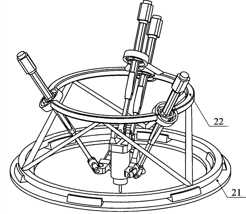
[0025] The structure of a multi-axis linkage device based on parallel modules in this embodiment is as follows figure 2 As shown, the multi-axis linkage device is different from Embodiment 1 in that: the multi-axis linkage device also includes a circular guide rail 21 and a kinematic pair. There is one kinematic pair, which is a rotary pair connected between the fixed platform 22 and the annular guide rail 21, and the rotary pair is driven. The device can realize five-axis linkage control of three degrees of freedom of movement and two degrees of freedom of rotation.

Embodiment 3

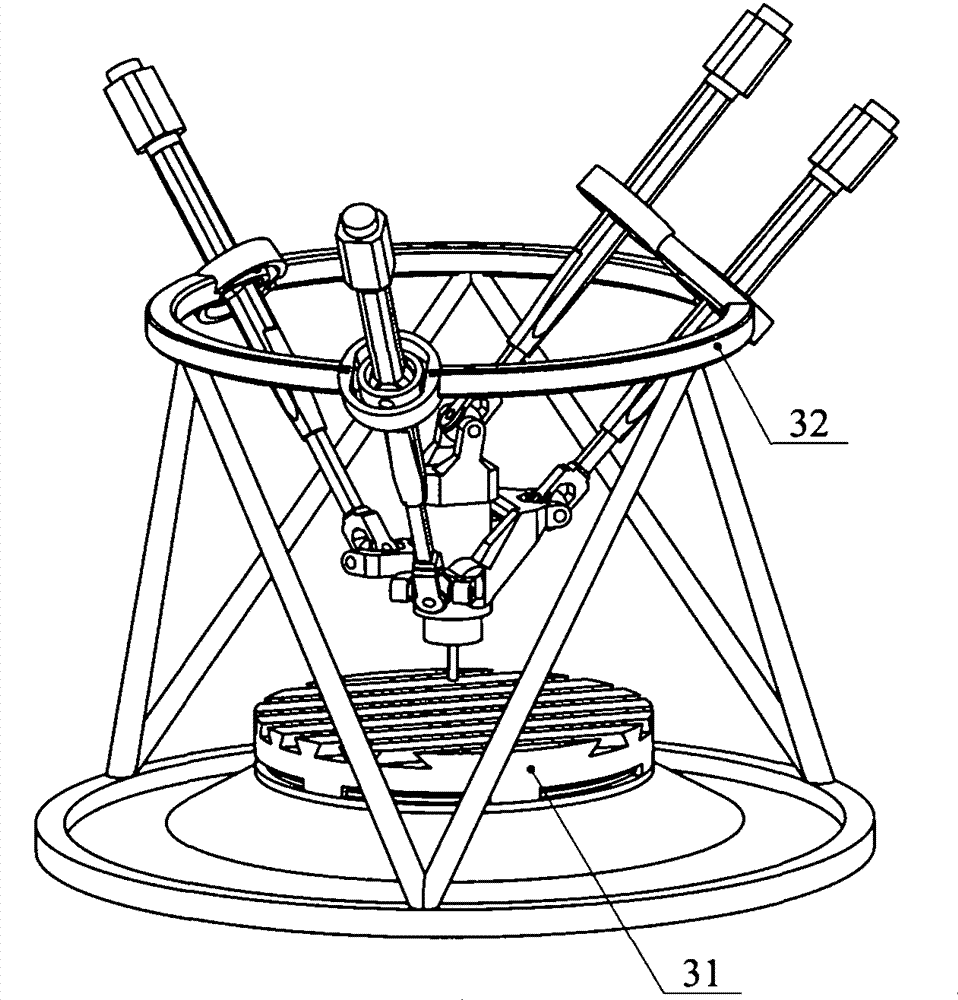
[0027] The structure of a multi-axis linkage device based on parallel modules in this embodiment is as follows image 3 As shown, the multi-axis linkage device is different from Embodiment 1 in that: the multi-axis linkage device also includes a turntable 31 and a kinematic pair. There is one kinematic pair, which is a rotary pair connected between the fixed platform 32 and the turntable 31, and the rotary pair is driven. The device can realize five-axis linkage control of three degrees of freedom of movement and two degrees of freedom of rotation.


PUM


Abstract

The invention relates to a multi-axis linkage based on modules in parallel and belongs to the technical field of manufacturing of numerical-control devices. The multi-axis linkage comprises a movable platform, a fixed platform, a U-shaped frame, a first branched hinge, a second branched hinge, a third branched hinge and a fourth branched hinge, wherein the first, second and third branched hinges are connected between the fixed platform and the U-shaped frame, and the fourth branched hinge is connected between the movable platform and the fixed platform. The multi-axis linkage is characterized in that the first, second and third branched hinges are respectively connected with the fixed platform and the U-shaped frame, the U-shaped frame is connected with the movable platform through revolute pairs, the fourth branched hinge is connected with the fixed platform and the movable platform to form a spatial parallel closed-up mechanism, and three mobile degrees of freedom and one rotational degree of freedom can be realized by means of driving of four inputs. The multi-shaft linkage can further comprise an annual guide rail or a workbench, the spatial parallel closed-up mechanism and the annual guide rail or the workbench form a parallel serial device capable of realizing as many as five five-axis linkage. By the application of the multi-axis linkage, vertical and horizontal conversion can be realized, and higher rotating and outputting capabilities are achieved.

Description

technical field [0001] The invention belongs to the field of mechanical manufacturing, and in particular relates to a multi-axis linkage device based on parallel modules that can be applied to the field of numerical control device manufacturing. Background technique [0002] A parallel mechanism refers to a closed-loop mechanism composed of two or more kinematic branch chains. Because of its compact structure and easy modularization, it is also called a parallel module. Compared with the traditional series mechanism, the parallel mechanism also has the following advantages: large carrying capacity per unit weight, small mass of moving parts, easy to realize high-speed movement, etc. In recent years, parallel mechanisms with fewer degrees of freedom (parallel mechanisms with less than six degrees of freedom) have attracted more and more attention from researchers because of their easy realization of larger workspaces (especially rotating workspaces) and simple kinematics. Fa...

Claims


Application Information

Patent Timeline
Patent Type & Authority Applications(China)
IPC IPC(8): B23Q1/64
CPCB23Q1/64B23Q5/22B23Q1/5462
Inventor 谢福贵刘辛军周艳华汪劲松
Owner TSINGHUA UNIV
Learn More