Light-emitting diode

A technology of light-emitting diodes and plate tubes, applied in electrical components, electrical solid-state devices, circuits, etc., can solve the problems of short working life, unreliability, and reduced luminous brightness of LED chips.

Inactive Publication Date: 2014-04-30
李莹
View PDF0 Cites 0 Cited by
  • Summary
  • Abstract
  • Description
  • Claims
  • Application Information

AI Technical Summary

Problems solved by technology

Therefore, the heat release from the LED chip from the heat is performed only through the plated surface of the electrode pattern, so the heat release is hardly performed. As a result, the temperature of the LED chip is not reduced, and if the temperature of the LED chip is low, the luminous efficiency, in other words , the electro-optical conversion coefficient is relatively high. Therefore, the LED chip is heated, and there is a problem that the luminous brightness decreases
In addition, the operating life of the LED chip becomes relatively short when operating at a higher temperature. In addition, there is a problem that the transparent sealing body sealing the LED chip is discolored due to heat, and the transparency is lowered.
In addition, there is the problem that LED chips tend to have shorter working life and are less reliable when used in high output and high brightness applications

Method used


Image

  • Light-emitting diode
  • Light-emitting diode
  • Light-emitting diode

Examples


Embodiment Construction

[0016] A preferred embodiment of a light emitting diode according to the present invention will be explained with reference to the accompanying drawings.

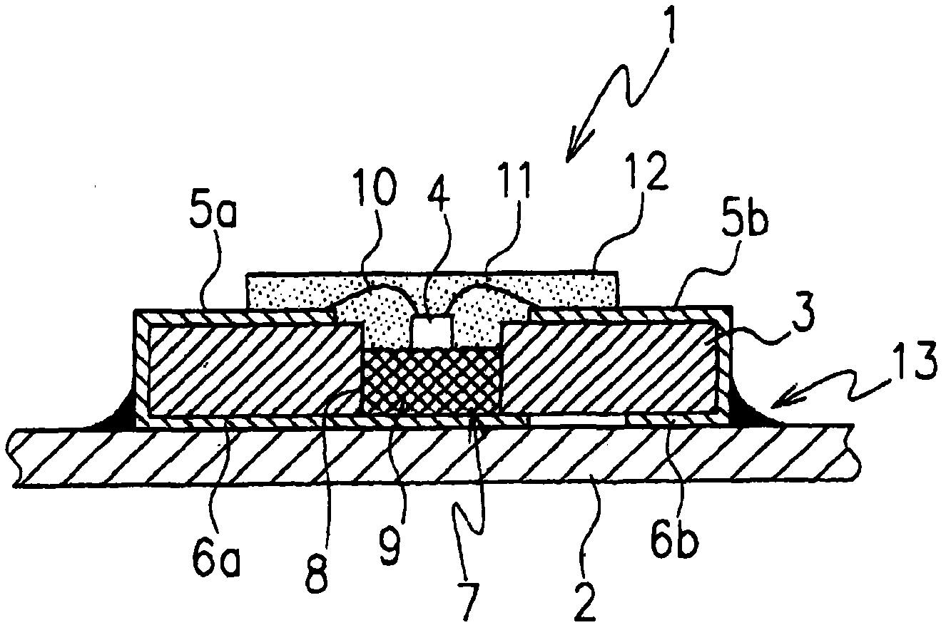
[0017] figure 1 The light emitting diode 1 of the first embodiment of the present invention will be described by way of example.

[0018] The light emitting diode 1 includes an LED chip 4, an insulating circuit substrate 3 in which the LED chip 4 is placed, and a printed wiring board 2. The insulating circuit substrate 3 is made of glass epoxy, silicone or the like.

[0019] Provided on the circuit substrate 3 are a pair of integrally formed upper and lower surface electrodes 5a, 6a and 5b, 6b.

[0020] The circuit substrate 3 has a heat radiating mechanism 7. The radiating mechanism 7 includes a heat radiating part 9, which is figure 1 In the embodiment shown in FIG. When the heat radiation member 9 is inserted in the storage portion 8, the heat radiation member 9 is arranged to contact the surface of the printed wiri...


PUM


Abstract

A light-emitting diode includes a circuit substrate, an LED chip, a heat radiation component which is arranged on the circuit substrate and supports the LED chip and receives heat from an LED and radiates the heat; and a sealing body which is arranged on the LED chip and coats the LED chip.

Description

technical field [0001] The invention relates to light emitting diodes for commercial devices such as personal computers, printers, PDAs (Personal Digital Assistants), facsimiles, pagers, and mobile phones, and more particularly, to light emitting diodes having an excellent heat-releasing effect. Background technique [0002] Conventionally, in surface mount light-emitting diodes that pursue slimming and miniaturization of electron devices, there is a known structure in which LED chips are mounted on electrode patterns formed on the upper surface of a glass epoxy resin substrate, and the transparent resin is covered with Provided on a substrate to seal the LED chip. [0003] image 3 As an example, the light-emitting diode 30 disclosed in this patent document is illustrated. In the structure that the light-emitting diode 30 has, the upper surface electrodes 32a, 32b and the lower surface electrodes 33a, 33b integrated and plated on the circuit substrate 3 are patterned to sur...

Claims


Application Information

Patent Timeline
Patent Type & Authority Applications(China)
IPC IPC(8): H01L33/48H01L33/64
CPCH01L2224/48091H01L2924/181H01L33/641H01L33/56H01L33/647
Inventor 李莹
Owner 李莹
Why Eureka
Try Eureka