
CD machine

A technology for optical disc drives and optical discs, which is applied to instruments, record carrier structural parts, and reduction of physical parameters of carriers, etc., can solve problems such as weight increase and overall size increase of notebook PCs, avoid heat accumulation, and achieve excellent heat release characteristics. Effect

Inactive Publication Date: 2005-05-04
SANYO ELECTRIC CO LTD
View PDF1 Cites 4 Cited by
  • Summary
  • Abstract
  • Description
  • Claims
  • Application Information

AI Technical Summary

Problems solved by technology

In an optical disk drive for a notebook PC, expanding the installation space of the components leads to an increase in the overall size of the notebook PC
In addition, in such a notebook type PC, the weight increases
Such a device is not designed / manufactured since such a situation is contrary to the requirements of users of notebook PCs

Method used


Image

  • CD machine
  • CD machine
  • CD machine

Examples


Embodiment Construction

[0054] An embodiment of the optical disk drive of the present invention will be described below with reference to the accompanying drawings.

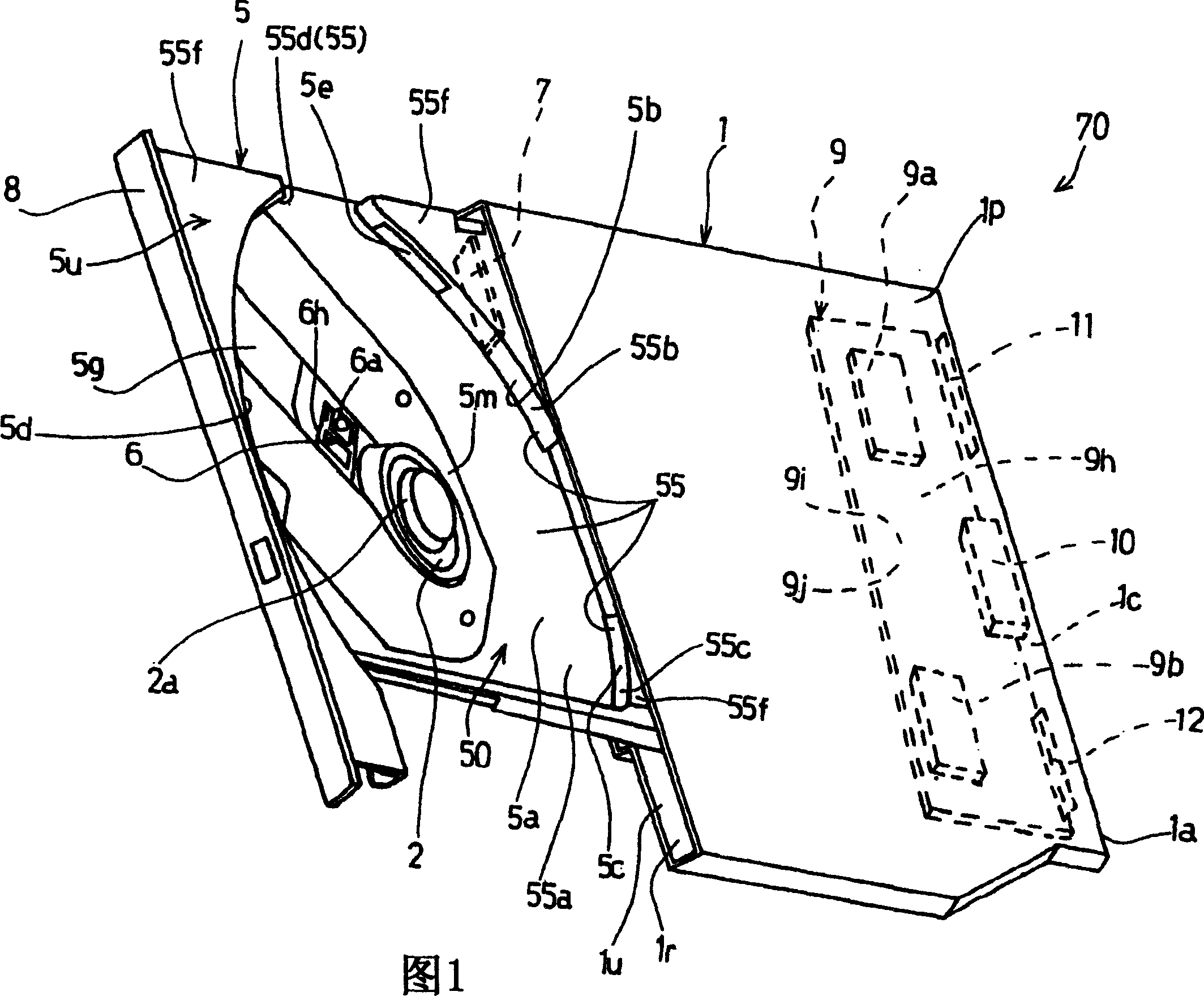
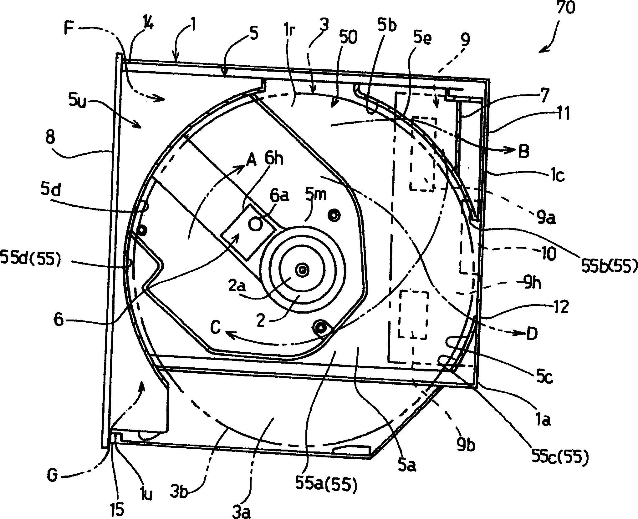
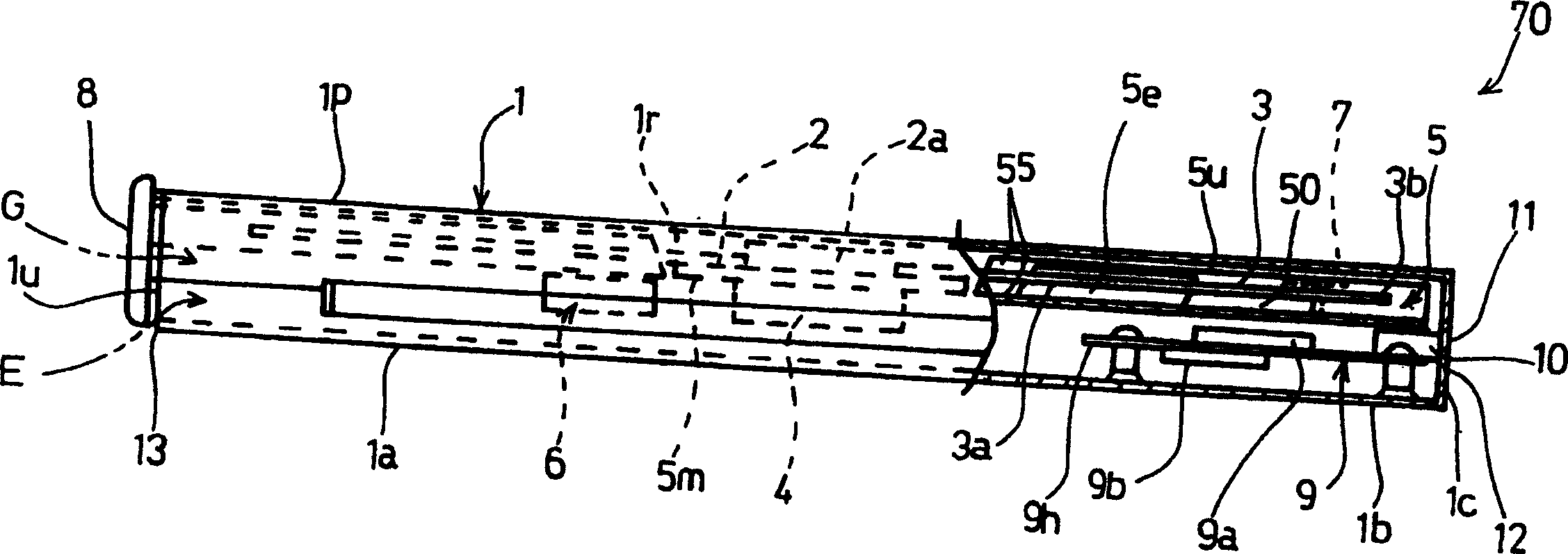
[0055] FIG. 1 is a perspective view showing an embodiment of an optical disc player of the present invention, figure 2 It is an explanatory diagram showing the state in which the tray is received inside the main body of the optical disc drive, image 3 It is an explanatory diagram showing the state that a part of the optical disc drive was removed, Figure 4 for image 3 An enlarged view of the main part of . Each figure will be specifically described below, and FIG. 1 is a perspective view showing a state in which a tray 5 in an optical disc drive 70 is ejected from the optical disc drive 1 . in addition, figure 2 It is a plan sectional view of main parts showing a state in which the tray 5 of FIG. 1 is inserted into the operating position of the main body 1 of the disc player. in addition, image 3 for viewing from the side fig...


PUM


Abstract

A disk drive 70 is provided with: a disk drive main body 1; a tray 5 which is openable or closable with respect to the disk drive main body; and a disk mounting section 50 which is provided on the tray to mount a disk. When a disk is located inside walls 55 that form the disk mounting section and the disk is rotated, air flow is generated in the disk mounting section. An escape port 5e is provided on the walls that form the tray to pass the air flow from the inside of the walls to the outside of the walls, and ejection ports 11 and 12 are provided on the disk drive main body to eject air in the disk drive main body. The escape port is provided at a position where an air flow is formed from the front side of the tray to the back side of the tray. The ejection port 11 is arranged at the back side of the disk drive main body. The disk drive main body having the tray can be mounted on a thin notebook type computer.

Description

technical field [0001] The present invention relates to an optical disc player in which, along with the rotation of the optical disc, the heat release of electric / electronic parts such as a substrate, a pickup, etc. is promoted to be cooled. Background technique [0002] An optical disc player that uses a light beam such as a laser to perform a signal reading operation or the like is widespread. The optical disc used in the optical disc drive is, for example, CD (compact disc) or DVD (digital versatile disc / digital video disc). "CD" is an abbreviation for "compact disc". In addition, "DVD" is an abbreviation for "digital versatile disc", or "digital video disc". [0003] As optical discs such as CDs and DVDs, for example, read-only optical discs such as CD-ROM and DVD-ROM, write-once discs such as CD-R and DVD±R, CD-RW, DVD±RW, DVD- Various optical discs such as a writeable / deletable / rewritable optical disc such as a RAM. These optical discs form a medium in which proces...

Claims


Application Information

Patent Timeline
IPC IPC(8): G11B33/14G11B25/04G11B33/00G11B33/02
Inventor 桥本光宏关根英夫青木武
Owner SANYO ELECTRIC CO LTD
Learn More