
Non-disturbance multi-level compensation circuit for power factor of AC power system

A power system and power factor technology, applied in reactive power compensation, reactive power adjustment/elimination/compensation, sustainable manufacturing/processing, etc., can solve problems such as power grid harmonic pollution, and achieve good versatility and high cost performance Effect

Active Publication Date: 2015-09-02
NANJING DING CHUN ELECTRIC
View PDF5 Cites 0 Cited by
  • Summary
  • Abstract
  • Description
  • Claims
  • Application Information

AI Technical Summary

Problems solved by technology

The disadvantages of the existing schemes are: firstly, a single capacitor can only achieve an ideal compensation effect for one point; secondly, the phase-shifting switching type will generate additional harmonic pollution to the power grid

Method used


Image

  • Non-disturbance multi-level compensation circuit for power factor of AC power system
  • Non-disturbance multi-level compensation circuit for power factor of AC power system
  • Non-disturbance multi-level compensation circuit for power factor of AC power system

Examples


Embodiment Construction

[0012] The present invention will be further described below in conjunction with accompanying drawing.

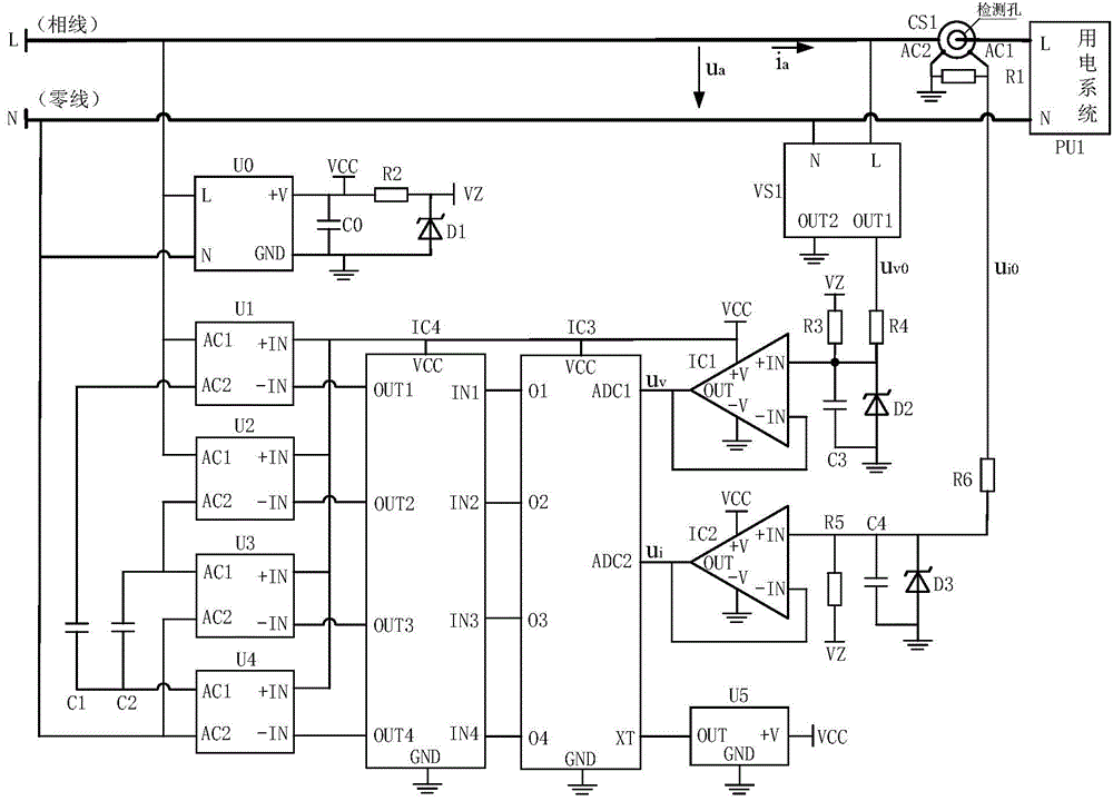
[0013] Such as figure 1 As shown, the non-disturbance multi-stage compensation circuit for the power factor of the AC power system includes a stabilized power supply circuit, a phase voltage and current signal conditioning circuit, and a compensation control circuit.

[0014] The regulated power supply circuit includes a regulated power supply module U0, a power supply capacitor C0, a regulated resistor R2, and a reference tube D1. The phase power supply terminal L of the regulated power supply module U0 is connected to the phase voltage terminal L of the power grid. The N terminal of the neutral line terminal is connected to the N terminal of the neutral line terminal of the power grid, the output power terminal +V terminal of the regulated power supply module U0 is connected to the positive terminal VCC terminal of the regulated power supply, one end of the power supply c...


PUM


Abstract

The invention relates to a non-disturbance multi-level compensating circuit for an AC electricity utilization system power factor. The non-disturbance multi-level compensating circuit comprises a stabilized voltage supply circuit, a phase voltage and current signal conditioning circuit and a compensation control circuit and specifically comprises a voltage transformer VS1, a current transformer CS1, a voltage follower IC1, a current follower IC2, a processor IC3, a drive chip IC4, a stabilized voltage supply module U0, a large solid-state relay U1, a small solid-state relay U2, a middle solid-state relay U3, a lower solid-state relay U4, a large compensation capacitor C1, a small compensation capacitor C2, a reference tube D1, an upper stabilivolt D2, a lower stabilivolt D3, a load resistor R1 and the like. According to the non-disturbance multi-level compensating circuit for the AC electricity utilization system power factor, non-disturbance combination switching on a grid is performed on the two compensation capacitors based on the four zero passing type AC solid-state relays so as to achieve four-level compensation control on the power factor, the requirement for power factor compensation control of most of AC loads can be met, and the method is high in cost performance, good in universality, safe and reliable.

Description

technical field [0001] The invention belongs to the field of industrial measurement and control, and relates to a circuit, in particular to a non-disturbance multi-level compensation circuit for the power factor of an AC power system, which is suitable for the application of automatic power factor compensation control for AC inductive loads, so as to improve power supply, Power efficiency. Background technique [0002] Most of the AC loads are inductive loads, and the current phase lags behind the voltage phase, and the power factor of the power supply and power system is an important indicator of the quality of power operation. At present, the commonly used schemes for improving the power factor are: first, when the power factor is detected to be low to a certain extent, each phase is connected in parallel with a compensation capacitor for compensating the power factor of the inductive load; Thyristor switching compensation capacitors, namely: each compensation capacitor u...

Claims


Application Information

Patent Timeline
Patent Type & Authority Patents(China)
IPC IPC(8): H02J3/18
CPCY02E40/30Y02P80/10
Inventor 陈德传卢玲范利良
Owner NANJING DING CHUN ELECTRIC
Learn More