Triangular distribution ring array electromagnetic shielding light window connected by circumscribed rings with sub-rings

An electromagnetic shielding and circular array technology, applied in the fields of magnetic field/electric field shielding, electrical components, etc., can solve the problems of concentrated stray light distribution and low imaging quality, and achieve the effect of improving uniformity and electromagnetic shielding effect.

Active Publication Date: 2015-07-29
HARBIN INST OF TECH
View PDF13 Cites 0 Cited by
  • Summary
  • Abstract
  • Description
  • Claims
  • Application Information

AI Technical Summary

Problems solved by technology

[0019] The purpose of the present invention is to overcome the deficiencies of the above-mentioned existing optical window electromagnetic shielding technical solutions, especially for the existence of advanced To solve the problem of relatively concentrated stray light distribution caused by sub-diffraction, a circumscribed ring connected with a triangular distribution ring array electromagnetic shielding light window with sub-rings is developed to achieve depth homogenization and extremely low imaging quality of high-order diffraction. purpose of influence

Method used


Image

  • Triangular distribution ring array electromagnetic shielding light window connected by circumscribed rings with sub-rings
  • Triangular distribution ring array electromagnetic shielding light window connected by circumscribed rings with sub-rings
  • Triangular distribution ring array electromagnetic shielding light window connected by circumscribed rings with sub-rings

Examples


Embodiment Construction

[0055] The following further describes the present invention with reference to the drawings and preferred embodiments:

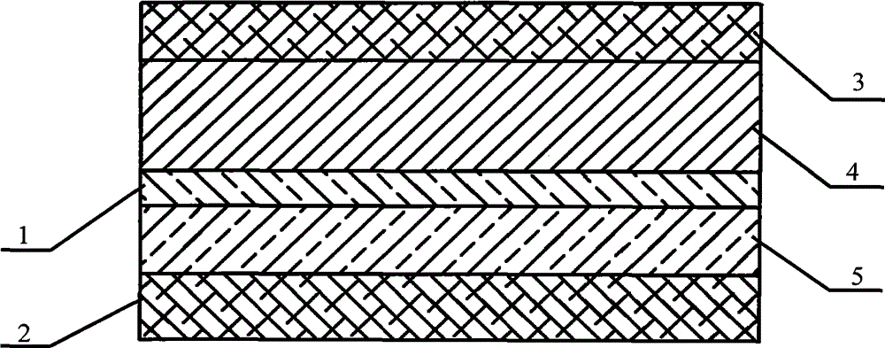
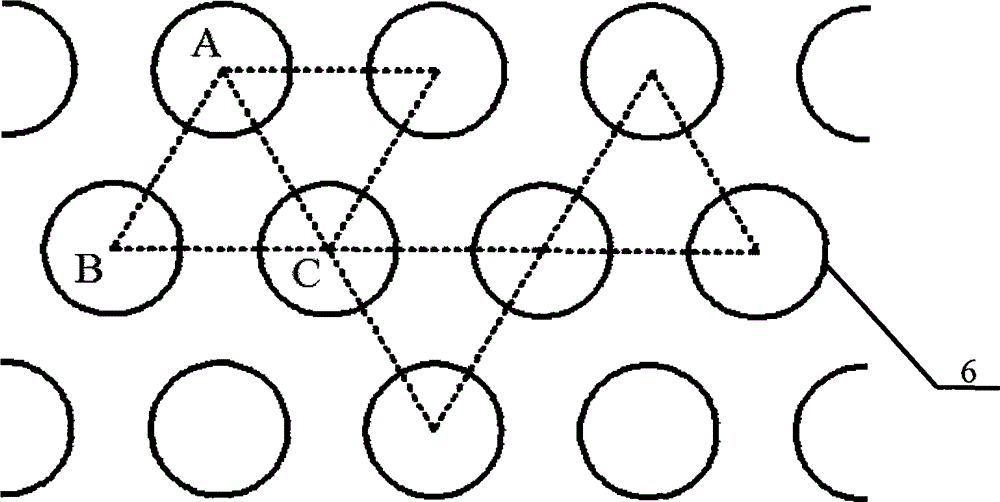
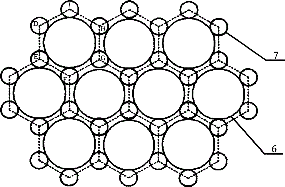
[0056] The circumscribed circular ring connects the triangular distributed circular ring array electromagnetic shielding light window with sub-rings, which is characterized in that the metal grid 5 in the electromagnetic shielding light window is composed of three metal circular rings with different diameters as the basic circular ring 6 and the connection The ring 7 and the filled ring 8 are arranged in an equilateral triangle, a regular hexagon with a common edge, and a regular hexagon with a vertex arranged in close contact to form a two-dimensional grid and loaded on the surface of the transparent substrate of the light window; the same diameter The metal rings are evenly separated. On the outside of each basic ring 6, there are 6 equally spaced connecting rings 7 and 6 equally spaced filled rings 8 that are connected to the outer tangent; in each basic ring...


PUM


Abstract

The invention provides an electromagnetic shielding optical window based on a triangularly-distributed circular ring array with sub circular rings and externally-tangent circular ring connection, and belongs to the technical field of electromagnetic shielding. Three kinds of metal circular rings with different diameters serve as basic circular rings, connecting circular rings and filling circular rings respectively and are ranked in an equilateral triangle mode, in a regular hexagon co-side mode and in a regular hexagon co-peak mode and tightly connected and distributed to form a two-dimensional mesh, and then the two-dimensional mesh is loaded to the surface of a transparent substrate of the optical window. The metal circular rings with the same diameter are separated, the outer side of each basic circular ring is provided with six connecting circular rings which are distributed at equal intervals and six filling circular rings which are distributed at equal intervals, wherein the six connecting circular rings and the six filling circular rings are communicated with the basic circular ring in an externally-tangent mode. The sub circular rings which are communicated with the basic circular rings in an internally-tangent mode are arranged inside the basic circular rings. It is guaranteed that all the circular rings are mutually conductive by overlapping lines or arranging metal which guarantees reliable electrical connection between metal ring points of tangency at joints where the circular rings are tangently communicated. Through the metal mesh structure, distribution unevenness of high-level diffraction light intensity of meshes can be remarkably reduced, stray light caused by diffraction is more evenly distributed, and the influence on imaging is smaller.

Description

Technical field [0001] The invention belongs to the field of electromagnetic shielding of optically transparent parts, and particularly relates to an electromagnetic shielding light window of a triangular distributed ring array with sub-rings connected with an circumscribed ring. Background technique [0002] With the broadening and increasing of the intensity of electromagnetic wave applications, the requirements for electromagnetic shielding light windows used in aerospace equipment, advanced optical instruments, communication equipment, medical diagnostic equipment and security facilities are getting higher and higher, mainly for light windows. It has a super wide-band electromagnetic shielding ability, but also has a very high light transmittance. The less impact on optical imaging, observation and detection, the better. For example, the optical windows of aircraft in the field of aerospace equipment must achieve high-quality isolation of electromagnetic signals inside and ou...

Claims


Application Information

Patent Timeline
Patent Type & Authority Patents(China)
IPC IPC(8): H05K9/00
Inventor 陆振刚谭久彬
Owner HARBIN INST OF TECH
Why Eureka
Try Eureka