
Gap control system and method for turbine engine

A turbine engine and control system technology, applied to engine components, machines/engines, mechanical equipment, etc., can solve problems such as unsatisfactory control of turbine blade tip clearance

Active Publication Date: 2014-05-07
AECC COMML AIRCRAFT ENGINE CO LTD
View PDF7 Cites 18 Cited by
  • Summary
  • Abstract
  • Description
  • Claims
  • Application Information

AI Technical Summary

Problems solved by technology

[0009] The purpose of the present invention is to propose a clearance control system of a turbine engine and a clearance control method of a turbine engine applied to the clearance control system of a turbine engine, which solves the technical problem that the control effect of the turbine blade tip clearance in the prior art is not ideal enough

Method used


Image

  • Gap control system and method for turbine engine
  • Gap control system and method for turbine engine
  • Gap control system and method for turbine engine

Examples


Embodiment Construction

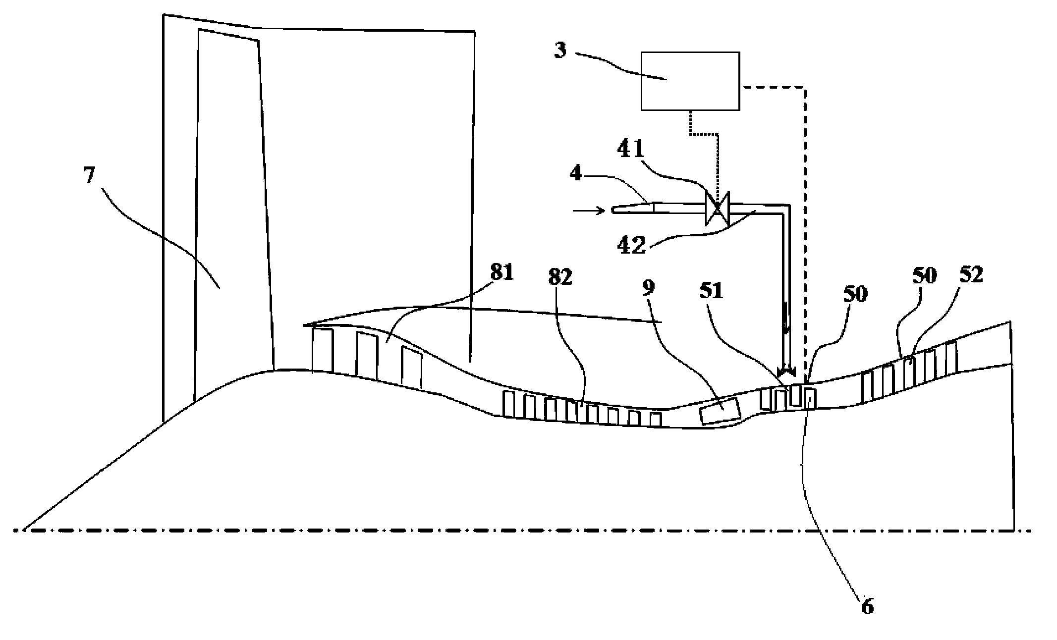
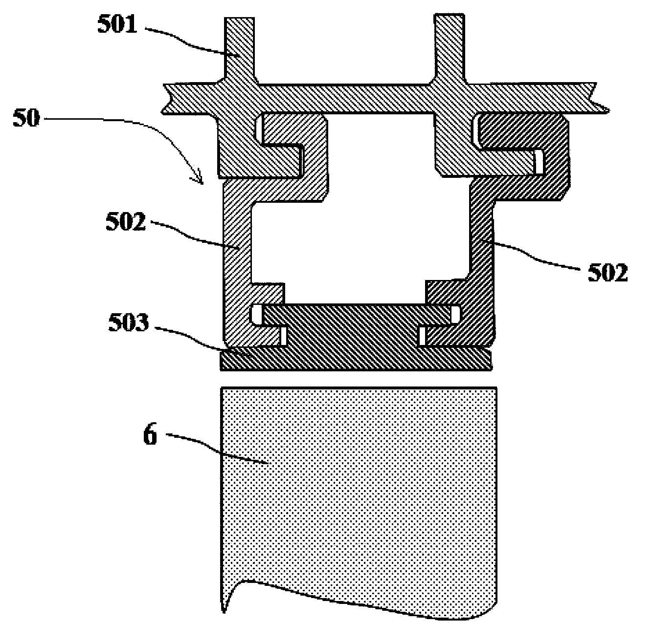
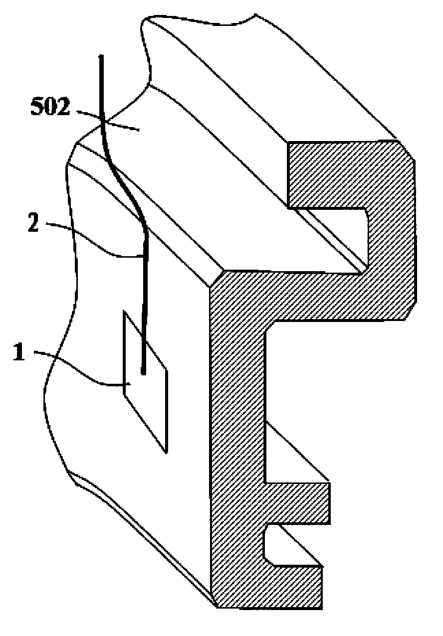
[0072] Below through the accompanying drawings Figure 1 to Figure 5 As well as listing some optional embodiments of the present invention, the technical solutions (including preferred technical solutions) of the present invention are further described in detail. It should be noted that: any technical feature and any technical solution in this embodiment are one or more of a variety of optional technical features or optional technical solutions. All the alternative technical features and alternative technical solutions of the present invention are cited, and it is not convenient for the implementation of each technical feature to emphasize that it is one of the optional multiple implementation modes, so those skilled in the art should know: Any technical features and any technical solutions in the embodiments do not limit the protection scope of the present invention, and the protection scope of the present invention should include any alternative technical solutions that thos...


PUM


Abstract

The invention discloses a gap control system and method for a turbine engine, and relates to the technical field of aircraft engines. The gap control system and method solve the problem that in the prior art, the control effect of the blade tip gap of a turbine is not ideal. The gap control system of the turbine engine comprises a turbine casing detection device, a turbine rotor detection device, a control device and a cooling fluid conveying device, wherein the turbine casing detection device is used for detecting the radial deformation of a turbine casing in the working process of the turbine engine and inputting the detection result into the control device; the control device is used for calculating the actual gap size between a blade tip of a turbine rotor and the turbine casing according to the original gap size between the blade tip of the turbine rotor and the turbine casing, a value of the radial deformation of the turbine casing, a rotating speed value and a temperature value in the assembly process. By the adoption of the gap control system and method for the turbine engine, the control accuracy of the gas size between the blade tip of the turbine rotor and the turbine casing is improved.

Description

technical field [0001] The invention relates to the technical field of aeroengines, in particular to a clearance control system of a turbine engine and a clearance control method of a turbine engine applied to the clearance control system of a turbine engine. Background technique [0002] Due to the incongruity of deformation between the turbine rotor and the turbine casing (or casing, stator) in the transient process of the aero turbine engine, in the static state, the tip of the rotor blade and the turbine casing need to be pre-stressed. Keep a large turbine blade tip clearance in the cold state so that the rotor and the turbine case will not collide with each other, but a large blade tip clearance will increase the fuel consumption rate of the engine in steady state operation. Therefore, civil aeroengines usually need to adopt Measures to keep the tip clearance optimal when the engine is running steadily. [0003] The main method of controlling the gap between the turbin...

Claims


Application Information

Patent Timeline
IPC IPC(8): F01D11/24
Inventor 顾伟陈涛乔剑
Owner AECC COMML AIRCRAFT ENGINE CO LTD
Learn More