Handheld dust collector

A vacuum cleaner and hand-held technology, applied in the field of hand-held vacuum cleaners, can solve the problems of long air flow channel, reduce the air flow intensity of the cyclone separator, and large volume, and achieve the effect of small suction loss and small and compact overall layout

Inactive Publication Date: 2014-05-14
ECOVACS ROBOTICS (SUZHOU ) CO LTD
View PDF12 Cites 109 Cited by
  • Summary
  • Abstract
  • Description
  • Claims
  • Application Information

AI Technical Summary

Problems solved by technology

[0003] Although this arrangement is convenient for the user to hold the vacuum cleaner, there are still some disadvantages. For example, when the cyclone separator in CN101489454B has multiple stages, its volume is relatively large; for example, when the cyclone separator and t

Method used


Image

  • Handheld dust collector
  • Handheld dust collector
  • Handheld dust collector

Examples


Embodiment Construction

[0020] In order to make the object, technical solution and advantages of the present invention clearer, the present invention will be described in detail below in conjunction with the accompanying drawings and specific embodiments.

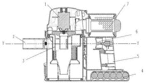
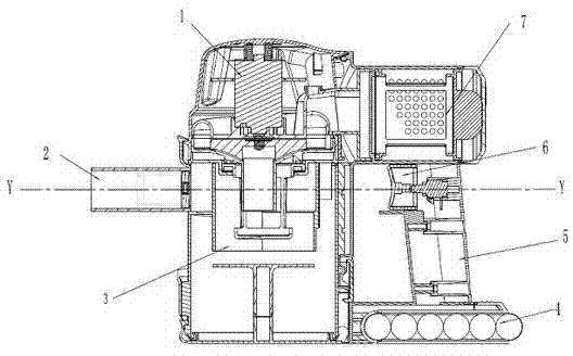
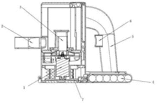
[0021] figure 1 It is the first embodiment of the present invention. As shown in the figure, the handheld vacuum cleaner includes an airflow generator assembly 1 , a suction pipe 2 , a cyclone separator assembly 3 , a power supply assembly 4 , a handle 5 , a trigger switch 6 , and a filter assembly 7 . The suction duct 2 has a longitudinal axis Y, said suction duct 2 having a suction opening. Based on the longitudinal axis Y, the vertical direction figure 1 The upside direction is above the hand-held vacuum cleaner, below Figure 2 to Figure 4 in the same. The airflow generator assembly 1 is used to generate airflow flowing along the suction duct. The cyclone separator assembly 3 communicates with the suction pipe 2 and is used to separate th...


PUM


Abstract

The invention provides a handheld dust collector which comprises a sucking-in pipeline, an air flow generator component, a cyclone separator component, a filter component, a power supply component and a handle. The sucking-in pipeline has a longitudinal axis. The air flow generator component generates air flow which flows along the sucking-in pipeline. The cyclone separator component is communicated with the sucking-in pipeline and is used for separating dust which is sucked in from air flow. The filter component is arranged in the handheld dust collector. The power supply component provides power for the air flow generator component. The handle is used for a user to hold. The air flow generator component and the cyclone separator component are arrayed in the direction perpendicular to the longitudinal axis. Compared with the prior art, an air flow generator and a cyclone separator are arranged up and down, so that whole arrangement is small, exquisite and compact, the air flow generator and the cyclone separator are directly communicated, and accordingly the sucking force of the dust collector is strong.

Description

technical field [0001] The invention relates to a hand-held vacuum cleaner, in particular to a hand-held vacuum cleaner with a cyclone separator assembly. Background technique [0002] A hand-held vacuum cleaner with a cyclone assembly typically includes an airflow generator assembly including a suction duct with a suction opening, a cyclone assembly, a power supply, a handle, a filter, etc. In the prior art, the layout of these components is often as disclosed in CN101489454B, that is: 1. The air flow generator 35 and the power supply 32 are respectively located at the upper end and the lower end of the handle 28; 2. The filter 42 is located at the cyclone separator device and the main body 3. The cyclone separator and the main body are generally arranged along the horizontal direction. [0003] Although this arrangement is convenient for users to hold the vacuum cleaner, there are still some disadvantages. For example, when the cyclone separator has multiple stages in CN1...

Claims


Application Information

Patent Timeline
IPC IPC(8): A47L5/24A47L9/16
Inventor 王寿木程文杰
Owner ECOVACS ROBOTICS (SUZHOU ) CO LTD
Why Eureka
Try Eureka