Dust collector main machine

A technology for vacuum cleaners and hosts, which is applied in the direction of vacuum cleaners, suction filters, handles, etc. It can solve problems such as unsmooth airflow, large suction loss, and non-disassembly, and achieve the effects of reasonable structural layout, small suction loss, and high suction power.

Pending Publication Date: 2020-05-01
JASHEN SUZHOU TECH CO LTD
View PDF0 Cites 0 Cited by
  • Summary
  • Abstract
  • Description
  • Claims
  • Application Information

AI Technical Summary

Problems solved by technology

[0002] The motor of existing vacuum cleaners is generally located above or below the dust cup, and the battery is located below the handle and cannot be disassembled; the air duct design is S-shaped, the air flow is not smooth, the distance between the motor and the air inlet is long, the suction loss is large, and the product structure layout is generally comparative. Bulky, not very practical, and inconvenient to use

Method used


Image

  • Dust collector main machine
  • Dust collector main machine

Examples


Embodiment 1

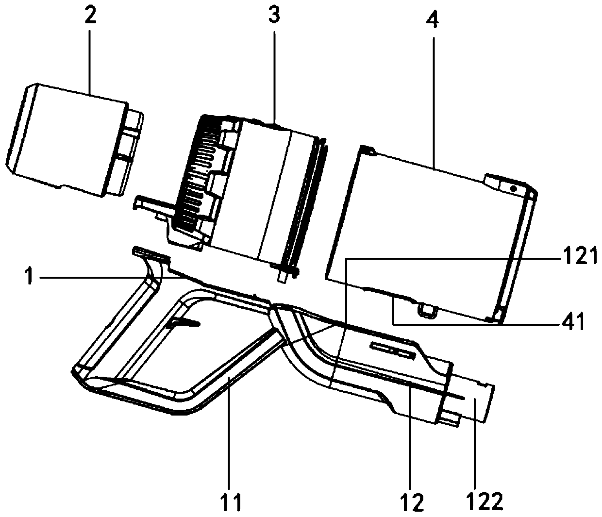
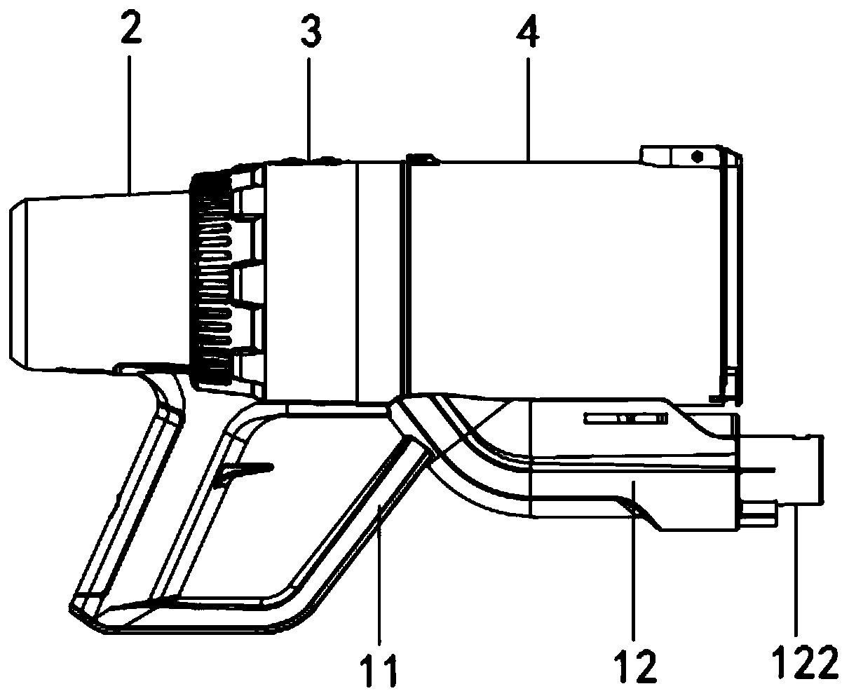
[0022] see Figure 1 to Figure 2 , this embodiment provides a vacuum cleaner main unit, first of all, a mounting base 1, a battery 2, a motor 3 and a dust cup 4 are provided, the battery 2, the motor 3 and the dust cup 4 are all installed on the mounting base 1, and the mounting base 1 is provided with There is a handle 11 and an air inlet pipe 12, the air inlet pipe 12 is fixedly connected to the handle 11, the motor 3 is detachably installed on the mounting base 1, and the position of the motor 3 corresponds to the position of the handle 11, and the battery 2 is detachably installed on the The first end of the motor 3 and the dust cup 4 are detachably mounted on the second end of the motor 3 , and the position of the dust cup 4 corresponds to the position of the air inlet pipe 12 .

[0023] continue to see Figure 1 to Figure 2 , the battery 2, the motor 3 and the dust cup 4 are located on the same axis, the battery 2, the motor 3 and the dust cup 4 are all located above th...

Embodiment 2

[0030] see Figure 1 to Figure 2 , the figure shows a vacuum cleaner main unit provided by Embodiment 2 of the present invention. On the basis of the above-mentioned embodiments, this embodiment further makes the following technical solutions as improvements: the air inlet pipe 12 is provided with a second A tuyere 121, the dust cup 4 is provided with a second tuyere 41 matching the first tuyere 121, the first tuyere 121 is located on the upper surface of the air inlet pipe 12, the second tuyere 41 is located on the lower surface of the dust cup 4, the first tuyere 121 1. An air duct is formed between the second tuyere 41 and the pipe mouth 122 of the air inlet pipe 12, and the wind force enters the dust cup 4 after passing through the air duct. This air duct is a trumpet structure, and the pipe mouth 122 is the entrance of the air duct. It is the outlet of the air duct, and the size of the nozzle 122 is smaller than that of the second air outlet 41 , so the wind speed at the ...

Embodiment 3

[0032] see Figure 1 to Figure 2 , the figure shows a vacuum cleaner main unit provided by the third embodiment of the present invention. On the basis of the above-mentioned embodiments, this embodiment further makes the following technical solutions as improvements: the air inlet pipe 12 is provided with a second A tuyere 121, the second tuyere 41 matching the first tuyere 121 is opened on the dust cup 4, and an arc-shaped limiting plate is respectively arranged on opposite sides of the first tuyere 121, and the two arc-shaped limiting plates are respectively wrapped in dust On the opposite side walls of the cup 4, on the one hand, the positional stability of the dust cup 4 is improved, and on the other hand, the leakage of wind force can be avoided.


PUM


Abstract

The invention provides a dust collector main machine. Firstly, a mounting base, a battery, a motor and a dust cup are arranged; the battery, the motor and the dust cup are all mounted on the mountingbase; a handle and an air inlet pipe are arranged on the installation base, the air inlet pipe is fixedly connected to the handle, the motor is detachably arranged on the installation base, the position of the motor corresponds to the position of the handle, the battery is detachably arranged at the first end of the motor, the dust cup is detachably arranged at the second end of the motor, and theposition of the dust cup corresponds to the position of the air inlet pipe. Compared with the prior art, the suction loss of the dust collector is reduced, the suction power is improved, the weight distribution of the dust collector is more uniform, and more labor is saved in the dust collection process of a handheld dust collector.

Description

technical field [0001] The invention relates to a vacuum cleaner, in particular to a vacuum cleaner host. Background technique [0002] The motor of existing vacuum cleaners is generally located above or below the dust cup, and the battery is located below the handle and cannot be disassembled; the air duct design is S-shaped, the air flow is not smooth, the distance between the motor and the air inlet is long, the suction loss is large, and the product structure layout is generally comparative. It is bulky, not practical, and inconvenient to use. Contents of the invention [0003] In view of this, the present invention provides a main body of a vacuum cleaner, which reduces the suction loss of the vacuum cleaner and increases the suction power compared with the prior art, so that the weight distribution of the vacuum cleaner is more uniform, and the hand-held vacuum cleaner is more efficient in the process of dust collection. To save effort. [0004] For this reason, th...

Claims


Application Information

Patent Timeline
Patent Type & Authority Applications(China)
IPC IPC(8): A47L5/24A47L9/00A47L9/10A47L9/28A47L9/32
CPCA47L5/24A47L9/00A47L9/10A47L9/28A47L9/2884A47L9/322A47L9/1409A47L9/1463A47L9/22
Inventor 张祺聂权洪纪乔梁成至
Owner JASHEN SUZHOU TECH CO LTD
Why Eureka
Try Eureka