Cavity structure of microwave rice cooker

A microwave and cavity technology, applied in the field of microwave heating products, can solve the problems of uneven distribution, local temperature rise on the surface of the pipe, poor stability of the output efficiency of the microwave component 6, etc.

Active Publication Date: 2015-08-26
GUANGDONG MIDEA KITCHEN APPLIANCES MFG CO LTD +1
View PDF5 Cites 18 Cited by
  • Summary
  • Abstract
  • Description
  • Claims
  • Application Information

AI Technical Summary

Problems solved by technology

Due to the large volume of the cavity, the length of the waveguide assembly 6 is relatively long. When the microwave is introduced into the bottom of the cavity from the magnetron 11 installed sideways through the waveguide assembly 6, and then fed into the microwave cavity, the microwave conduction distance is long, resulting in Microwave transmission loss is large
Specifically, when the microwaves generated by the magnetron 11 are transmitted in the microwave tube, if the transmission path is long, it is easy to form microwave concentration, so that the distribution of microwaves in the microwave transmission cavity in the waveguide is uneven, and it is easy to cause multiple microwave

Method used


Image

  • Cavity structure of microwave rice cooker
  • Cavity structure of microwave rice cooker
  • Cavity structure of microwave rice cooker

Examples


Embodiment Construction

[0073] The specific embodiments of the present invention will be described in detail below with reference to the accompanying drawings. It should be understood that the specific embodiments described herein are only used to illustrate and explain the present invention, and not to limit the present invention.

[0074] In the present invention, if there is no explanation to the contrary, the orientation words used such as "up, down, top, bottom, longitudinal" are usually directed to the directions shown in the drawings or refer to vertical, vertical or The terms used to describe the mutual positional relationship of the components in the direction of gravity; “lateral” is usually referred to the left and right directions of the drawings along the paper. "Inner and outer" generally refers to the inside and outside of the chamber relative to the chamber or the radial inside and outside relative to the center of the circle.

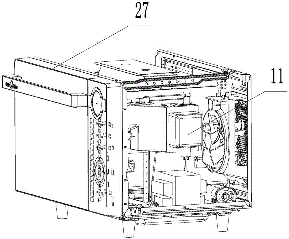
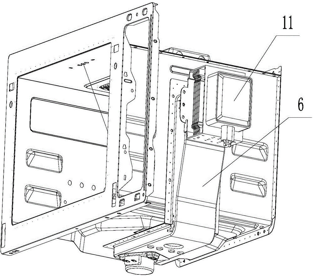
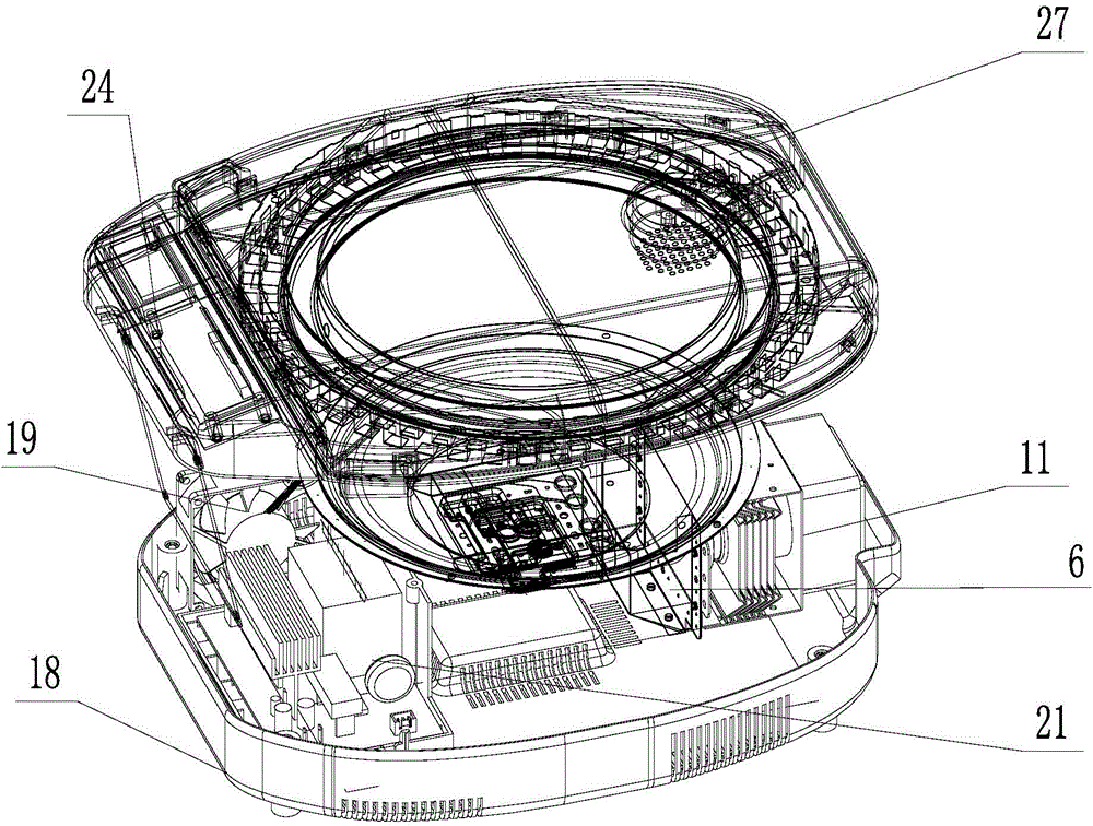
[0075] Such as Figure 3 to Figure 8 As shown, the present i...


PUM


Abstract

The invention discloses a cavity structure of a microwave rice cooker. The cavity structure comprises a cavity body (2), a microwave transmitting mechanism and a stirring component, wherein the cavity body is internally provided with a cooking cavity, a top opening of the cooking cavity is formed in the top cover (1), and the microwave conveying mechanism comprises a waveguide component (6) with a transverse part and a decurrent part; a magnetron (11) is arranged on the decurrent part, the microwave is` input into the microwave transmitting cavity (63) by virtue of a microwave inlet (12), and the transverse part is connected with the bottom of a bottom cover; the microwave is fed into the cooking cavity by virtue of a microwave feeding port (9), the stirring component comprises a microwave stirring plate (4) and a stirring motor (7), the microwave stirring plate is disc-shaped and is arranged on the inner side of the bottom cover (5); the stirring motor is arranged on the bottom of the transverse part, and the microwave stirring plate is driven to rotate by virtue of the microwave stirring plate so as to stir the microwave fed into the cooking cavity. The cavity structure is small in body type and cavity body, compact in structure, and capable of favorably realizing the microwave heating for the cooking cavity.

Description

Technical field [0001] The invention belongs to the field of household appliances, and specifically relates to a microwave heating product. Background technique [0002] A common microwave oven in daily life is a modern cooking stove that uses microwaves to heat food. Its power range is about 500 to 1000 watts, such as figure 1 As shown, it is generally composed of a power supply, a magnetron 11, a control circuit, and a cooking cavity. The power supply provides a high voltage of about 4000 volts to the magnetron 11, and the magnetron 11 continuously generates microwaves under the excitation of the power supply, and then passes through the waveguide assembly 6 to couple into the cooking cavity. Near the entrance of the cooking cavity, there is a rotatable stirrer. Since the stirrer is a fan-shaped metal sheet, it will reflect microwaves in all directions after rotating, so the microwave energy can be evenly distributed in the cooking cavity. Thereby heating the food. [0003] Suc...

Claims


Application Information

Patent Timeline
IPC IPC(8): F24C7/02F24C15/00
CPCF24C15/00H05B6/64
Inventor 陈茂顺彭定元唐相伟栾春王轩刘民勇
Owner GUANGDONG MIDEA KITCHEN APPLIANCES MFG CO LTD
Why Eureka
Try Eureka