

Sending method, device and user equipment
A sending method and technology of user equipment, applied in the field of communication, can solve problems such as inability to initiate priority
- Summary
- Abstract
- Description
- Claims
- Application Information
AI Technical Summary
Problems solved by technology
Method used
Image

Examples
example 1
[0065] Figure 6 It is a flow chart of the request sending method according to Example 1 of the present invention, such as Figure 6 As shown, the method mainly includes steps S602 to S614.
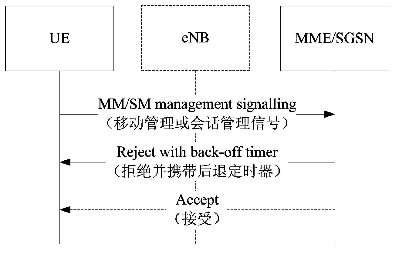
[0066] In step S602, the dual-priority UE sends signaling to the network side.
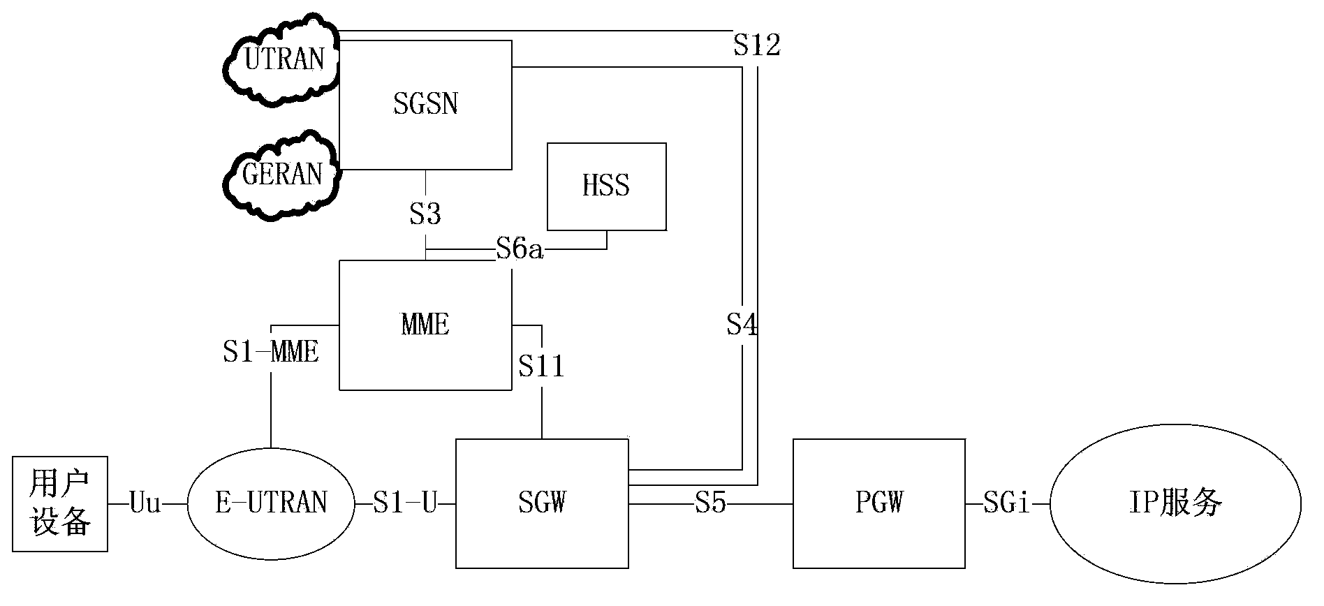
[0067] In the embodiment of the present invention, the signaling sent by the UE is Non Access Stratum (Non Access Stratum, NAS for short) signaling, which is irrelevant to the wireless access technology and independent of the functions and procedures related to wireless access. Signaling may include mobility management signaling and session management signaling. The network side may be the MME or SGSN in the core network. The foregoing signaling includes priority indication information, for example, indicating that the priority is low priority or normal priority.
[0068] In step S604, the network side judges whether there is congestion, if yes, execute step S606, otherwise, execute step S614.
[0069] I...
example 2
[0082] The scenario of this example is: the UE sends mobility management signaling to the network side. Figure 7 It is a flow chart of the sending method of the request according to Example 2 of the present invention, such as Figure 7 As shown, the method includes step S702 to step S714.
[0083] In step S702, the UE sends mobility management signaling to the network side.
[0084] In this step, mobility management signaling may include but not limited to: attach (attach), TAU / RAU / LAU, and service request (service request). The mobility management signaling may or may not contain APN information.
[0085] Step S704, the network side judges whether there is congestion, if yes, execute step S706, otherwise, execute step S714.
[0086] In the embodiment of the present invention, the network side is a core network, including but not limited to at least one of the following: MME / SGSN, Serving-GW, and PDN-Gate Way, P-GW. The congestion on the network side can be APN congestion...
example 3
[0104] The scenario of this example is: the UE sends session management signaling to the network side. Figure 8 It is a flow chart of the request sending method according to Example 3 of the present invention, such as Figure 8 As shown, the method includes step S802 to step S814.
[0105] In step S802, the UE sends session management signaling to the network side.
[0106] In this step, the session management signaling may include but not limited to: PDN connection, bearer resource allocation or bearer resource modification request, and the like. The session management signaling is aimed at the APN, that is, the signaling includes APN information.
[0107] In step S804, the network side judges whether there is congestion, if yes, execute step S806, otherwise, execute step S812.
[0108] In the embodiment of the present invention, the network side is a core network, including but not limited to at least one of the following: MME / SGSN, Serving-GW, and PDN-Gate Way (P-GW for...
PUM
 Abstract
Description
Claims
Application Information