Intelligent control system and control method for cockpit

An intelligent control system and cockpit technology, applied to aircraft parts, optical observation devices, transportation and packaging, etc., can solve the problems of drivers providing driving environment display, not solving blind spots in vision, and not having camera systems, so as to reduce driving discomfort Safety factors, improved driving experience, and the effect of a large viewing angle

Inactive Publication Date: 2016-03-02
盛凯
View PDF6 Cites 0 Cited by
  • Summary
  • Abstract
  • Description
  • Claims
  • Application Information

AI Technical Summary

Problems solved by technology

[0004] In the prior art, for example, the patent No. ZL201320079383.7 discloses a car surround camera system. The system captures images by installing multiple cameras on the vehicle body, so as to provide accident image evidence after an accident. The camera system does not have Providing the driver with a display of the driving environment does not solve the technical problem of blind spots; for example, the patent No. ZL201020239721.5 discloses a car navigation device using a transparent OLED screen as a window, which uses an OLED display as a window , associating OLED with GPS, so as to realize the function of car navigation on the car window. This patent uses the windshield as a navigation screen, and there is a view blocking during driving, and there are unsafe factors

Method used


Image

  • Intelligent control system and control method for cockpit
  • Intelligent control system and control method for cockpit
  • Intelligent control system and control method for cockpit

Examples


Embodiment 1

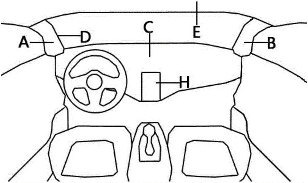
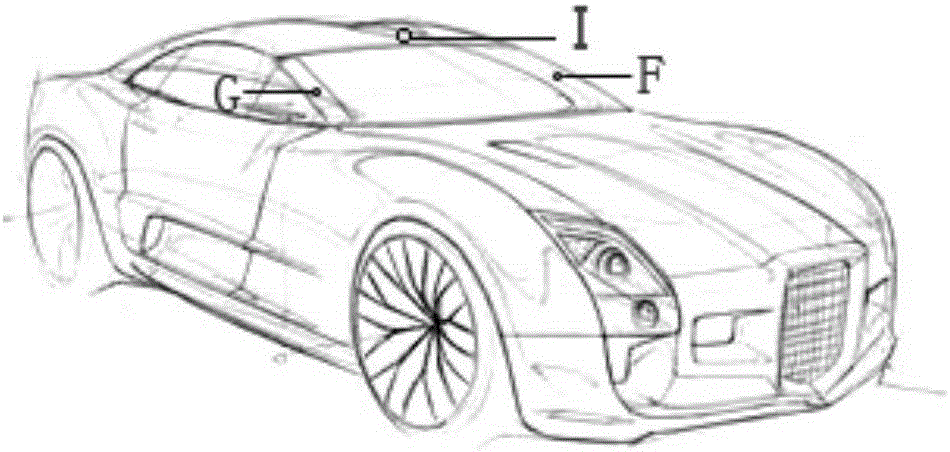
[0039] In this embodiment, the driving environment display and control system based on the general OLED curved surface is applied to the car, such as figure 1 and 2 As shown, a driving environment display and control system based on a general-purpose OLED curved surface includes a top-mounted infrared panoramic camera installed in the mounting hole on the outer surface I of the roof cover, and a camera mounted on the mounting hole on the outer surface F of the support column respectively. The support column infrared panoramic camera Ⅰ and the support column infrared panoramic camera II in the installation hole at G; it also includes the exterior OLED display screen Ⅰ bonded to the cockpit interior roof E and the cockpit support column blind area B respectively. The external scene OLED display screen II and external view OLED display screen III at D and the central control OLED display screen installed at C of the instrument panel area, PLC, and the data transmission interface ...

Embodiment 2

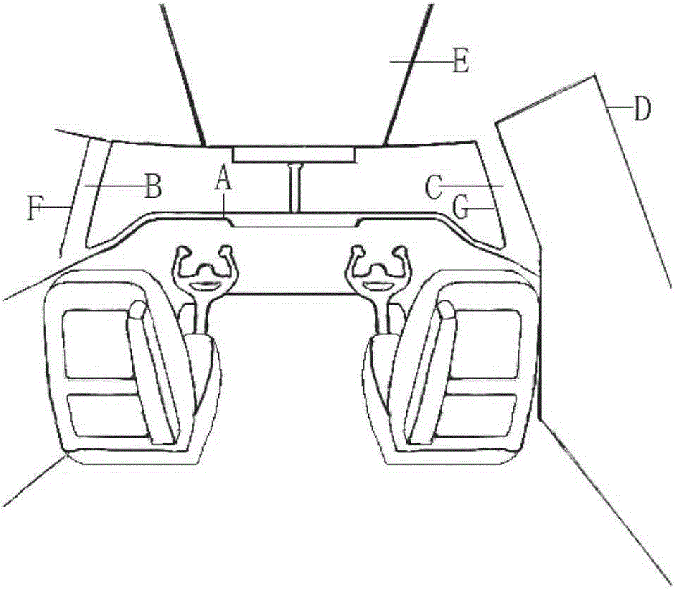
[0046] In this embodiment, the general OLED curved surface-based driving environment display and control system is applied to the aircraft, such as image 3 As shown, a driving environment display and control system based on a general-purpose OLED curved surface includes a support column infrared panoramic camera I and a support column infrared panoramic camera respectively installed in the mounting holes at F and G on the outer surface of the support column Ⅱ; also includes the exterior OLED display screen Ⅰ bonded at the top cover E of the cockpit, the exterior OLED display screen Ⅱ and the exterior OLED display screen Ⅲ respectively bonded at the blind areas B and D of the cockpit support column and installed on the The central control OLED display in the area A of the instrument panel, ARM; the support column camera Ⅰ and support column camera Ⅱ and the exterior display screen Ⅰ, exterior view display screen Ⅱ and exterior view display screen Ⅲ are respectively connected to...


PUM


Abstract

The invention provides an intelligent control system and method for a flight deck. The intelligent control system for the flight deck comprises a camera shooting unit, a displaying unit, a central processing unit and a data transmission interface, wherein the camera shooting unit is installed on the outer surface of the flight deck, and the displaying unit, the central processing unit and the data transmission interface are installed inside the flight deck. The intelligent control method for the flight deck includes the steps that A, the intelligent control system is applied for receiving a system starting instrument of a driver, starting the camera shooting unit and synchronously starting the displaying unit; B, the displaying unit synchronously displays environment colleted pictures shot by the camera shooting unit in real time; C, the central processing unit is started for collecting various driving parameters, and the collected parameters are operated and processed to be displayed on a center control display screen; D a fatigue driving monitoring alarm apparatus is started for monitoring fatigue state signals of the driver in real time. According to the intelligent control system and method, contradictions between traveling view maximization and vehicle structure safety are eliminated, the network technique is applied to driving to improve the driving intelligence, and the information interaction amount between people and driven vehicles is increased.

Description

technical field [0001] The invention relates to a real-time display system and a control method for shooting images, in particular to a camera and display system used in a cockpit and an intelligent control method thereof. Background technique [0002] With the continuous progress of economy and technology, the number of cars is increasing day by day. The progress of science and technology has led to the rapid development of the automobile industry. People have a new direction of thinking about the safety and pleasure of car driving experience. However, the support column between the roof cover and the car body between the front windshield cannot be removed, which will inevitably lead to blind spots in the driving process. Under the premise of safety guarantee, try to reduce the area of ​​the support column and reduce the blind area of ​​vision, so as to obtain the maximum visible field of vision when driving. However, this approach will undoubtedly reduce the safety of the ...

Claims


Application Information

Patent Timeline
Patent Type & Authority Patents(China)
IPC IPC(8): B60R11/02B60R11/04B60R1/00B64D47/08B64D43/00
Inventor 盛凯
Owner 盛凯
Why Eureka
Try Eureka