
Manually operated card reader

A card reader, manual technology, applied in the direction of instruments, electromagnetic radiation induction, computer components, etc., can solve the problems of high cost, large power consumption, etc., and achieve the effect of preventing piracy

Active Publication Date: 2014-05-28
HITACHI OMRON TERMINAL SOLUTIONS CORP
View PDF7 Cites 8 Cited by
  • Summary
  • Abstract
  • Description
  • Claims
  • Application Information

AI Technical Summary

Problems solved by technology

If actuators such as motors are used in this way, the size of the card reader will increase, the cost will increase, and the power consumption will increase.
In addition, it becomes an obstacle when installing a card reader on an inexpensive device or portable terminal that requires low price, small size, light weight, and power saving.

Method used


Image

  • Manually operated card reader
  • Manually operated card reader
  • Manually operated card reader

Examples


Embodiment Construction

[0050] Hereinafter, embodiments of the present invention will be described with reference to the drawings. In each figure, the same code|symbol is attached|subjected to the same part or a corresponding part.

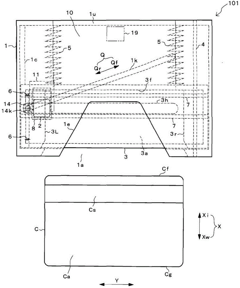
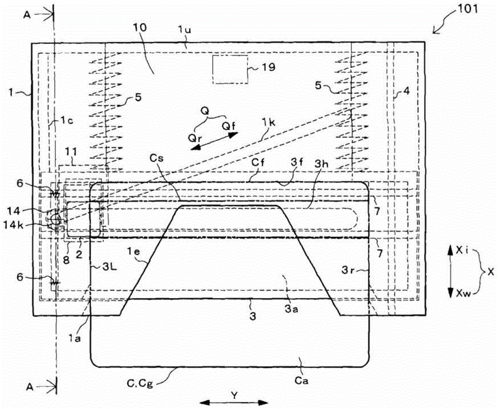
[0051] First, refer to Figure 1 to Figure 7 The structure of the manual card reader 101 of the first embodiment will be described.

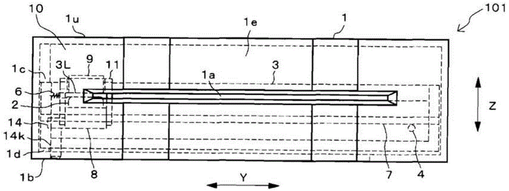
[0052] in addition, figure 1 It is a top view of the manual card reader 101. figure 2 It is a front view of the manual card reader 101. image 3 , Figure 5 as well as Image 6 It is a card insertion state diagram of the manual card reader 101, and the card insertion depth is different. Figure 4 Yes image 3 A-A sectional view of . Figure 7 Yes Image 6 The BB cross-sectional view.

[0053] The outer frame of the manual card reader 101 is constituted by the frame 1 . On the front of frame 1, such as figure 1 as well as figure 2 , etc., an insertion port 1a for inserting the card C in the short-side direction X is provided....


PUM


Abstract

A manually operated card reader can prevent skimming when a card is inserted and can move a magnetic head to read magnetic information of the card without using an actuator. The manually operated card reader (101) has an insertion opening (1a) allowing a card (C) to be inserted in a short edge direction (X), a magnetic head (2) reads magnetic information from a magnetic stripe (Cs) which is configured to extend in a long edge direction (Y) in the card (C), and a magnetic head moving mechanism (10). The magnetic head moving mechanism (10), through an inserting force when the card (C) is inserted in the short edge direction (X) from the insertion opening (1a), enables the magnetic head (2), in a state of being in contact with the magnetic stripe (Cs), to be moved from one end of the magnetic stripe (Cs) in the long edge direction (Y) in the card (C) to the other end.

Description

technical field [0001] The present invention relates to the structure of the insertion port in the manual card reader and the moving mechanism of the magnetic head. Background technique [0002] In recent years, a crime called skimming in which magnetic information recorded on a magnetic stripe of a card is stolen frequently occurs. The method is as follows, for example. [0003] The magnetic stripe extends along the long side of the card, and the card is inserted into the slot of the card reader in the long side direction, so an illegal reading device called a skimmer is installed in front of the slot. And, when the card is inserted from the insertion port in the longitudinal direction, the magnetic information is read from the magnetic stripe of the card by the magnetic head incorporated in the card reading cassette. [0004] As a countermeasure against skimming, there is a manual card reader in which a card is inserted in a short-side direction as disclosed in Patent Do...

Claims


Application Information

Patent Timeline
Patent Type & Authority Applications(China)
IPC IPC(8): G06K7/10G06K17/00
Inventor 影山岳志
Owner HITACHI OMRON TERMINAL SOLUTIONS CORP
Learn More