Wiretap demonstration device and method based on quantum key communication

A technology of quantum key and demonstration device, which is applied in the field of eavesdropping demonstration device based on quantum key communication, can solve problems such as inability to intuitively demonstrate eavesdropping and inability to intuitively demonstrate the security of quantum communication, and achieve intuitive security and simple method. intuitive effect

Active Publication Date: 2014-05-28
ANHUI QASKY QUANTUM SCI & TECH CO LTD
View PDF13 Cites 11 Cited by
  • Summary
  • Abstract
  • Description
  • Claims
  • Application Information

AI Technical Summary

Problems solved by technology

However, in the existing technology, it is generally impossible to intuitively demonstrate the security of quantum communication, and it is also impossible to intuitively demonstrate the process of eavesdropping

Method used


Image

  • Wiretap demonstration device and method based on quantum key communication
  • Wiretap demonstration device and method based on quantum key communication

Examples


Embodiment 1

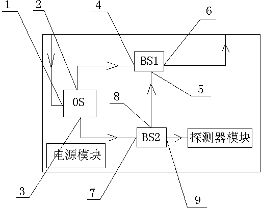
[0023] See figure 1 , The present eavesdropping demonstration device based on quantum key communication includes an optical switch OS for switching working modes, a first optical beam splitter BS1 for combining or splitting light, and for combining or splitting light. The branched second optical beam splitter BS2 and a synchronous detector for simulating eavesdropping information; the optical switch OS includes an optical input terminal 1, a first optical output terminal 2 and a second optical output terminal 3; The first optical beam splitter BS1 includes a first light entrance 4, a second light entrance 5, and a light output terminal 6; the second light beam splitter BS2 includes a light entrance 7, a first light exit 8 and a second light exit Port 9; the first light output end 2 is connected to the first light input end 4, the second light output end 3 is connected to the light input port 7, the first light output port 8 is connected to the second light input end 5, and the s...

Embodiment 2

[0033] This eavesdropping demonstration method based on quantum key communication includes the following steps:

[0034] Step 1. Input the light beam into the optical switch from the optical input end, and set the optical switch to the normal mode, so that the light beam passes through the optical switch and the first optical beam splitter in sequence, and then is emitted from the optical output end;

[0035] Step 2. Set the optical switch to eavesdropping mode so that the light beam is transmitted to the second optical beam splitter after passing through the optical switch. The second optical beam splitter divides the beam into two signals, one of which passes through the first optical beam splitter, From the optical output terminal to the receiving terminal, another signal enters the sync detector; when the sync detector detects the optical signal, the indicator light on the sync detector lights up.


PUM


Abstract

The invention discloses a wiretap demonstration device based on quantum key communication. The wiretap demonstration device comprises an optical switch OS, a first beam splitter BS1, a second beam splitter BS2 and a synchronous detector. The optical switch OS comprises a light input end, a first light output end and a second light output end. The first beam splitter BS1 comprises a first light inlet end, a second light inlet end and a light output end. The second beam splitter BS2 comprises a light inlet, a first light outlet and a second light outlet. The first light output end is connected with the first light inlet end, the second light output end is connected with the light inlet, the first light outlet is connected with the second light inlet end and the second light outlet is connected with the synchronous detector. The invention further discloses a wiretap demonstration method based on quantum key communication. The wiretap demonstration device and method based on quantum key communication can very visually display the safety of quantum communication information transmission, and the method is simple, visual, economical and practical.

Description

technical field [0001] The invention relates to an eavesdropping demonstration device and method used in quantum key communication, in particular to an eavesdropping demonstration device and method based on quantum key communication. Background technique [0002] Quantum key communication is based on the three laws of quantum science: measurement collapse theory, quantum non-cloning theory, and uncertainty principle. Based on the above three theories, the security and reliability of information transmitted by quantum key communication is better than that of classical communication. However, in the prior art, it is generally impossible to intuitively demonstrate the security of quantum communication, and it is also impossible to intuitively demonstrate the process of eavesdropping. Contents of the invention [0003] The technical problem solved by the present invention is to provide an eavesdropping demonstration device based on quantum key communication for the above-ment...

Claims


Application Information

Patent Timeline
Patent Type & Authority Applications(China)
IPC IPC(8): G09B19/00
Inventor 徐生福方子刘云苗春花韩正甫赵义博
Owner ANHUI QASKY QUANTUM SCI & TECH CO LTD
Why Eureka
Try Eureka