
A mounting bracket capable of changing the rotation angle

A technology of rotating angle and mounting bracket, which is applied in the direction of lighting devices, lighting auxiliary devices, lighting device components, etc., and can solve the problem that the light angle of the lamp cannot be adjusted.

Active Publication Date: 2016-05-11
SHENZHEN OCEANS KING LIGHTING ENG CO LTD +1
View PDF6 Cites 0 Cited by
  • Summary
  • Abstract
  • Description
  • Claims
  • Application Information

AI Technical Summary

Problems solved by technology

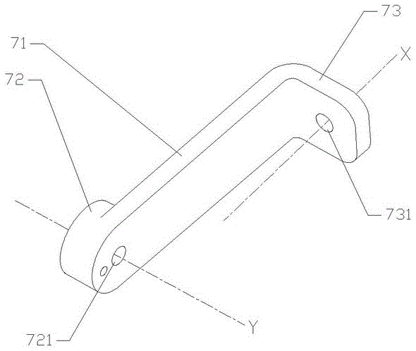
[0004] In order to solve the technical problem in the prior art that the light angle cannot be adjusted after the lamp is installed, the present invention provides a mounting bracket that can change the rotation angle, which is used to mount the device to be installed on the fixing device. The mounting bracket includes a A bracket rotating shaft that changes the rotation angle, the bracket rotating shaft includes: an intermediate shaft, a first connecting portion and a second connecting portion that are respectively arranged at both ends of the intermediate shaft and integrated with the intermediate shaft; There is a first through hole penetrating through the first connecting part, and a second through hole penetrating through the second connecting part is opened on the second connecting part, and the first axial direction of the axis of the first through hole is connected with the second through hole. The second axial direction of the hole axis is vertical; the first connecting piece passes through the first through hole and cooperates with the fixing piece to connect the bracket shaft to the device to be installed, which can change the rotation angle around the first axis; the second connecting piece Through the second through hole, the bracket rotating shaft can change the rotation angle around the second shaft and connect to the fixing device

Method used


Image

  • A mounting bracket capable of changing the rotation angle
  • A mounting bracket capable of changing the rotation angle
  • A mounting bracket capable of changing the rotation angle

Examples


Embodiment Construction

[0022] The following will clearly and completely describe the technical solutions in the embodiments of the present invention with reference to the drawings in the embodiments of the present invention.

[0023] Please also refer to Figure 2 to Figure 6 , the embodiment of the present invention provides a mounting bracket whose angle can be changed.

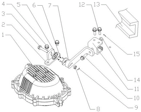
[0024] The invention discloses a mounting bracket capable of changing the rotation angle, which is used for mounting a device to be installed on a fixing device. Specifically, in this embodiment, the lamp is installed on the steel beam of the derrick or on the wall. Such as figure 2 As shown, it is a three-dimensional exploded view of the assembly and connection of the mounting bracket. The main part of the mounting bracket is the bracket shaft 7 that can change the rotation angle.

[0025] Such as image 3 As shown, the bracket rotating shaft 7 includes: an intermediate shaft 71 , a first connecting portion 72 and a second ...


PUM


Abstract

The invention provides an installation support with a changeable rotation angle. The installation support is used for installing a device to be installed to a fixed device, and comprises a support rotation shaft with a changeable rotation angle. The support rotation shaft comprises an intermediate shaft, a first connection portion and a second connection portion. The first connection portion and the second connection portion are arranged at the two ends of the intermediate shaft respectively and integrated with the intermediate shaft. The first connection portion is provided with a first through hole penetrating through the first connection portion, the second connection portion is provided with a second through hole penetrating through the second connection portion, and the first axial direction of the axis of the first through hole is perpendicular to the second axial direction of the axis of the second through hole. A first connection piece penetrates through the first through hole and is in fit with a fixing piece, and the support rotation shaft is changeably connected to a device to be installed by a first shaft rotation angle. Rotation angle of a second connection piece penetrates through the second through hole and enables the support rotation shaft to be changeably connected with the fixing device by a second shaft rotation angle. Due to change of the angle of the installation support, the installation angle of a lamp with the installation support can be adjusted at will.

Description

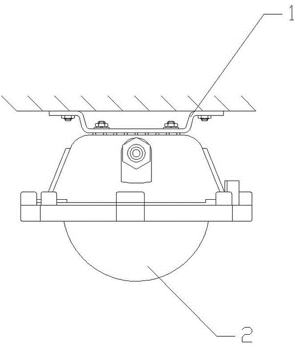
technical field [0001] The invention relates to a mounting bracket, in particular to a mounting bracket capable of changing the rotation angle used in lamp installation. Background technique [0002] The installation of existing lamps is usually equipped with different installation brackets according to different installation methods. For seat and side wall installations, such as figure 1 As shown, the mounting bracket 1 is fixed on the assembly base through two holes. Once the installation is completed, the light of the lamp 2 can only be irradiated vertically or horizontally, and the direction of the lamp cannot be adjusted arbitrarily. And, in this installation mode, the installation base must be drilled according to the size of the installation hole of the installation bracket before installation. For some derricks that cannot be drilled, the installation difficulty of the lamp is increased. Contents of the invention [0003] The purpose of the present invention is t...

Claims


Application Information

Patent Timeline
Patent Type & Authority Patents(China)
IPC IPC(8): F21V21/14
Inventor 周明杰李爱丽
Owner SHENZHEN OCEANS KING LIGHTING ENG CO LTD
Learn More