Internally-geared machine

A gear machine, internal gear pump technology, applied in mechanical equipment, machines/engines, rotary piston machines, etc., can solve the problem that the balance pressure is not constant

Active Publication Date: 2014-06-11
ROBERT BOSCH GMBH
View PDF5 Cites 0 Cited by
  • Summary
  • Abstract
  • Description
  • Claims
  • Application Information

AI Technical Summary

Problems solved by technology

The leakage depends on the wear, temperature and rotational speed of the internal gear machine, so the balance pressure is not constant

Method used


Image

  • Internally-geared machine
  • Internally-geared machine

Examples


Embodiment Construction

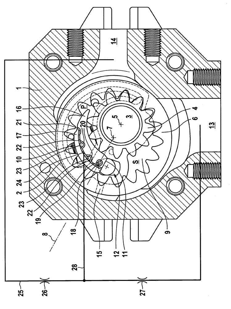
[0014] exist figure 1 The internal gear machine shown in has a housing, an annular middle part 1 of which can be seen. The central part 1 encloses a pump chamber 2 which is closed off by two side parts, not shown, of the housing. In both side parts, a drive shaft 3 is rotatably mounted. On the drive shaft 3 , an externally toothed pinion 4 is arranged in a rotationally fixed manner in the pump chamber 2 , the gear axis 5 of which coincides with the longitudinal axis of the drive shaft 3 .

[0015] The ring gear of pinion 4 has twelve teeth. The pinion is surrounded by an internally toothed ring gear 6 with eighteen teeth, the gear axis 7 of which runs parallel to and eccentrically to the gear axis 5 of the pinion. A center plane 8 extends through the gear axes 5 and 7 .

[0016] The ring gear 6 is mounted rotatably with its radially surrounding cylindrical shell surface in the corresponding circular pump chamber 2 of the central part. In the area of ​​both sides of the ce...


PUM


Abstract

The invention relates to an internally-geared machine, particularly an internal gear pump. The internally-geared machine comprises an externally toothed pinion and an internally toothed hollow wheel gear; a filling member, and a banking pin, wherein the externally toothed pinion and the internally toothed hollow wheel gear are meshed with each other and surrounds a crescent working zone; the filling member is approximate to crescent and disposed in the working zone; the point of the filling member is disposed at the first side of the center surface strutted by the axes of the two gears; the crescent working zone is divided into a low-pressure zone connected to a low-pressure connector, and a high-pressure zone connected to a high-pressure connector; the filling member comprises a sector section support squeezed to the gear ring of the pinion, and a sealing sector section adhered to a tooth crest of the hollow wheel gear; and the filling member is adhered to the banking pin through the wide end of the filling member. The high-pressure zone and the low-pressure zone are connected through a balance channel, a hydraulic pressure balanced fluid flows through the balance channel. Crosswise fluid can be branched and conduction to a balance cavity can be performed. The balance cavity is loaded through the balance pressure.

Description

technical field [0001] The invention relates to an internal gear machine, in particular an internal gear pump, having a housing; a pinion with external teeth rotatable about a first gear axis; A hollow gear with internal teeth meshed with the pinion, the hollow gear and the pinion enclose a crescent-shaped working area; there is an approximately half-crescent shape arranged between the pinion and the hollow gear filler in the working area, the pointed end of which is located on the first side of a central plane spanned by the two gear axes, and the crescent-shaped working area is divided into a A low-pressure area and a high-pressure area connected to the high-pressure connection, wherein the filler part is constructed in two parts and consists of a segment carrier pressed with its inner side onto the ring gear of the pinion and a A sealing sector resting on the tooth tips of the ring gear, and wherein a balancing chamber sealed with respect to the working area is formed betw...

Claims


Application Information

Patent Timeline
Patent Type & Authority Applications(China)
IPC IPC(8): F04C2/10F04C15/00
CPCF04C2270/585F04C2/101F04C15/0019F04C2270/165F04C2/086F04C2/10F04C2270/52
Inventor M.翁格尔
Owner ROBERT BOSCH GMBH
Why Eureka
Try Eureka