Dual hydraulic machine transmission

Inactive Publication Date: 2005-11-10
TORVEC INC
View PDF85 Cites 20 Cited by
  • Summary
  • Abstract
  • Description
  • Claims
  • Application Information

AI Technical Summary

Benefits of technology

[0017] The modular transmissions are described using various embodiments of hydraulic machines, all of which share a novel combination of simple structural features including elongated pistons reciprocating in a fixed cylinder block, cylinders provided with unique lubrication recesses, and shoes directly attached to each piston (without dog-bones) that make sliding contact with a rotating and nutating swash plate or, preferably, with the nutating-only wobbler portion of a split swash plate. Testing has verified that these simple structural features have synergistically resulted in a remarkably increased volumetric efficiency and such increase

Problems solved by technology

Although all-hydraulic transmissions have been contemplated for automobiles, the inefficiency of hydraulic transmissions in the prior art has made them impractical for use in automobiles.
Scaling a hydraulic transmission of the prior art for use in an automobile would produce an unacceptably large, heavy, and noisy transmission, and such transmissions would be larger, heavier, and noisier than the transmissions currently used in automobiles.
However, a major hurdle for implementation of HCCI technology in automobiles is a difficulty in controlling the combustion both at low and at high engine speeds.
Because of the incompressibility of liquids, the pressure and load duty cycles of these two different types of hydraulic machines are so radically different that designs for the gas compression type machines are inappropriate for use in the liquid-type machines, and visa versa.
However, these light

Method used


Image

  • Dual hydraulic machine transmission
  • Dual hydraulic machine transmission
  • Dual hydraulic machine transmission

Examples


Example

[0034] Initially, the following key features of the invention are described:

[0035] To meet the world's needs for oil conservation while, at the same time, not requiring changes that will cause a significant disturbance in the world's present allocation of fuels, the invention provides an all-hydraulic, gearless, infinitely variable transmission that uses known and tested hydraulic and electronic components.

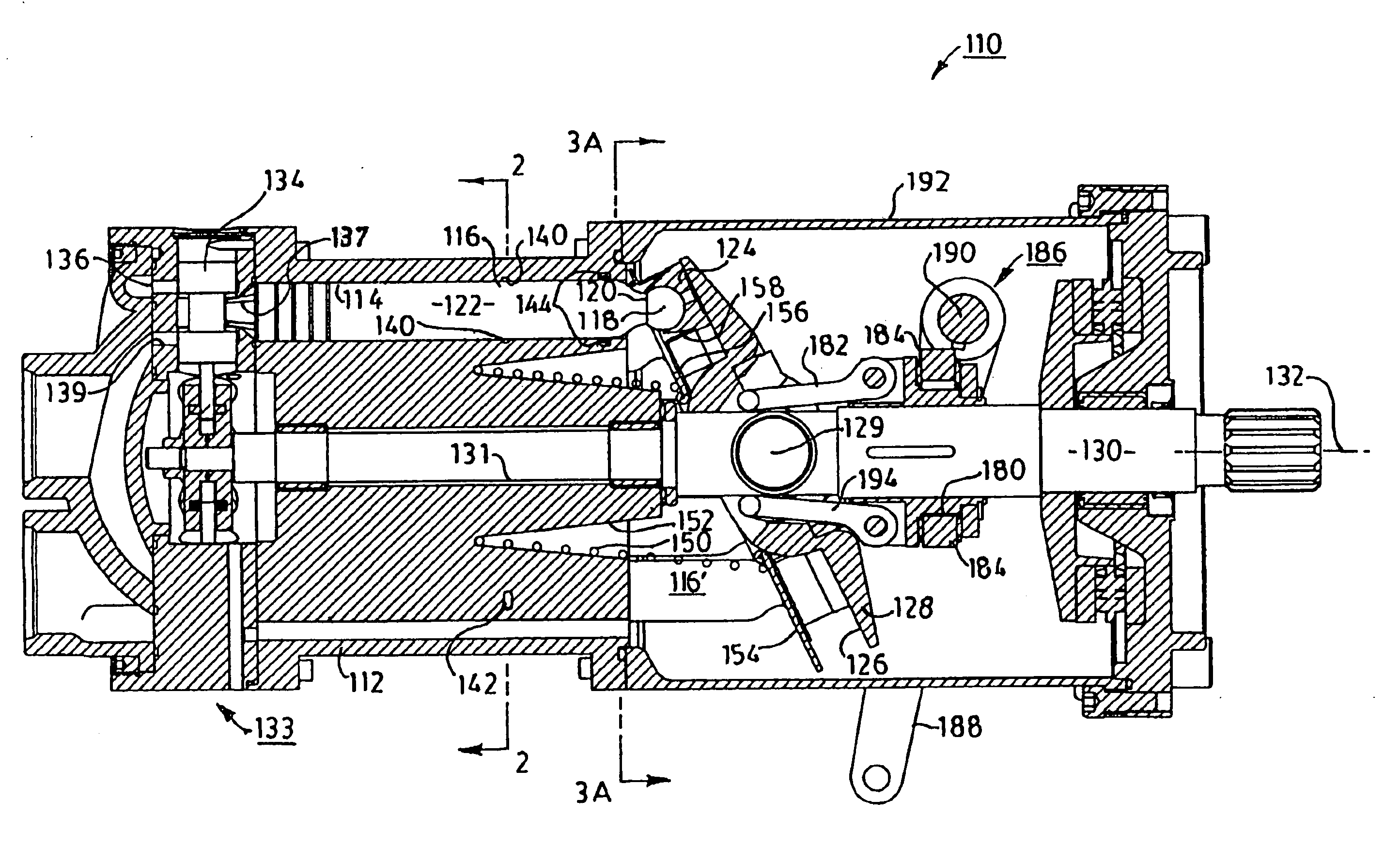
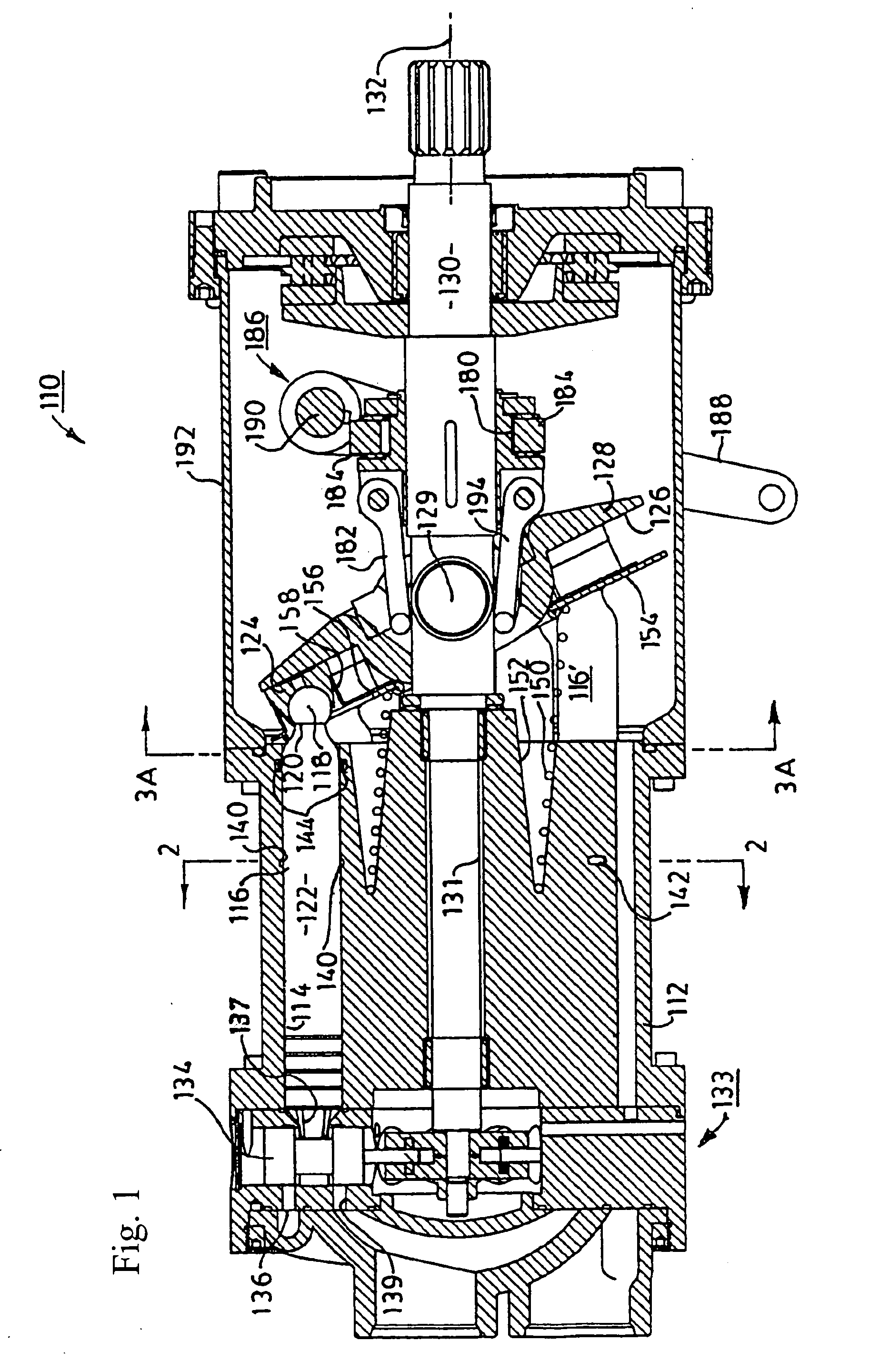
[0036] Since the hydraulics of a transmission of the present invention provide working torque at very low engine RPM's, a gasoline engine vehicle incorporating the present invention in place of the vehicle's original torque converter transmission operates at much lower engine speeds. This feature is due to the remarkable efficiencies that are achieved by using hydraulic machines having stationary cylinder blocks and rotating swash plates that vary through a wide continuum of angles, preferably from −25° to +25°.

[0037] A transmission of the present invention is directly coupled ...


PUM


Abstract

The modular transmission uses only a pair of small and light hydraulic machines of remarkably improved volumetric efficiency with pistons having body portions substantially as long as the axial length of the respective cylinders in which they reciprocate. The two hydraulic machines operate in a closed loop, one being used as a pump driven by the vehicle's engine, and the other used as a motor. Each machine has a fully articulatable swash plate. By computer control, the angles of the swash plates of the two machines are infinitely varied to provide an appropriate optimum ratio of engine/wheel speed for all conditions from start-up, city driving, hill climbing varied according to load and steepness, and over-drive for highway. This complete vehicle operation is attained while the vehicle's engine continues to operate at relatively constant speeds and relatively low RPM.

Description

REFERENCE TO RELATED APPLICATIONS [0001] This is a continuation-in-part patent application of co-pending application Ser. No. 10 / 789,739, filed Feb. 27, 2004, entitled “LONG-PISTON HYDRAULIC MACHINES”, which is a continuation-in-part of application Ser. No. 10 / 647,557, filed Aug. 25, 2003, entitled “LONG-PISTON HYDRAULIC MACHINES”, now abandoned, which was a continuation-in-part of parent patent application Ser. No. 10 / 229,407, filed Aug. 28, 2002, entitled “LONG-PISTON HYDRAULIC MACHINES”, now abandoned. The aforementioned applications are hereby incorporated herein by reference. [0002] The subject matter of this application is also related to the subject matter in co-pending application entitled “ORBITAL TRANSMISSION WITH GEARED OVERDRIVE”, filed on the same day as the present application. This application is herein incorporated by reference.FIELD OF THE INVENTION [0003] This invention relates to hydraulic transmissions used for vehicle locomotion and to liquid hydraulic pump / moto...

Claims


Application Information

Patent Timeline
IPC IPC(8): B60K17/00B60K17/10F04B1/12F04B27/10F16H39/14F16H47/04
CPCB60K17/105B60W10/06B60W30/1882F04B1/126F16H61/431F16H39/14F16H47/04F16H61/421F04B27/109F16H2059/6869F16H2059/6876
Inventor GLEASMAN, KEITH E.WRONA, MATTHEW R.
Owner TORVEC INC
Why Eureka
Try Eureka