Intake manifold

Active Publication Date: 2005-06-02
MITSUBISHI MOTORS CORP
View PDF0 Cites 1 Cited by
  • Summary
  • Abstract
  • Description
  • Claims
  • Application Information

AI Technical Summary

Benefits of technology

[0013] That is, the passage sectional area of the fourth portion of the branch pipe on the side of the surge tank, apart from the cylinder head of the engine, is kept at a relatively large constant value between the cylinder head and the surge tank, whereby the volumetric efficiency at the time of high speed of engine is easily increased. And the passage sectional area of the second portion

Problems solved by technology

But there is a problem that the volumetric effic

Method used


Image

  • Intake manifold
  • Intake manifold
  • Intake manifold

Examples


Example

[0023] In the following embodiments, like reference characters designate the same or similar parts throughout the figures.

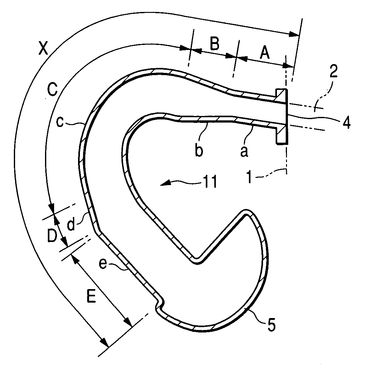
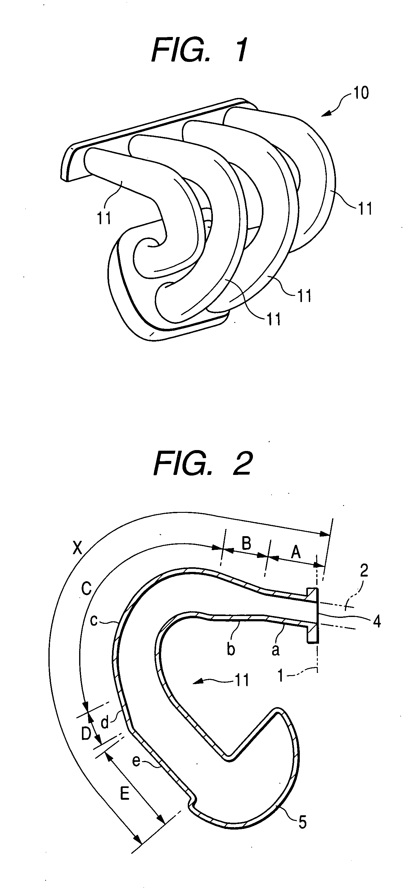
[0024] In FIGS. 1 to 3, an intake manifold 10 of a 4-cylinder engine has four branch pipes 11 corresponding to each cylinder, in which each branch pipe 11 connects an intake port 2 of a cylinder head 1 and a surge tank 5.

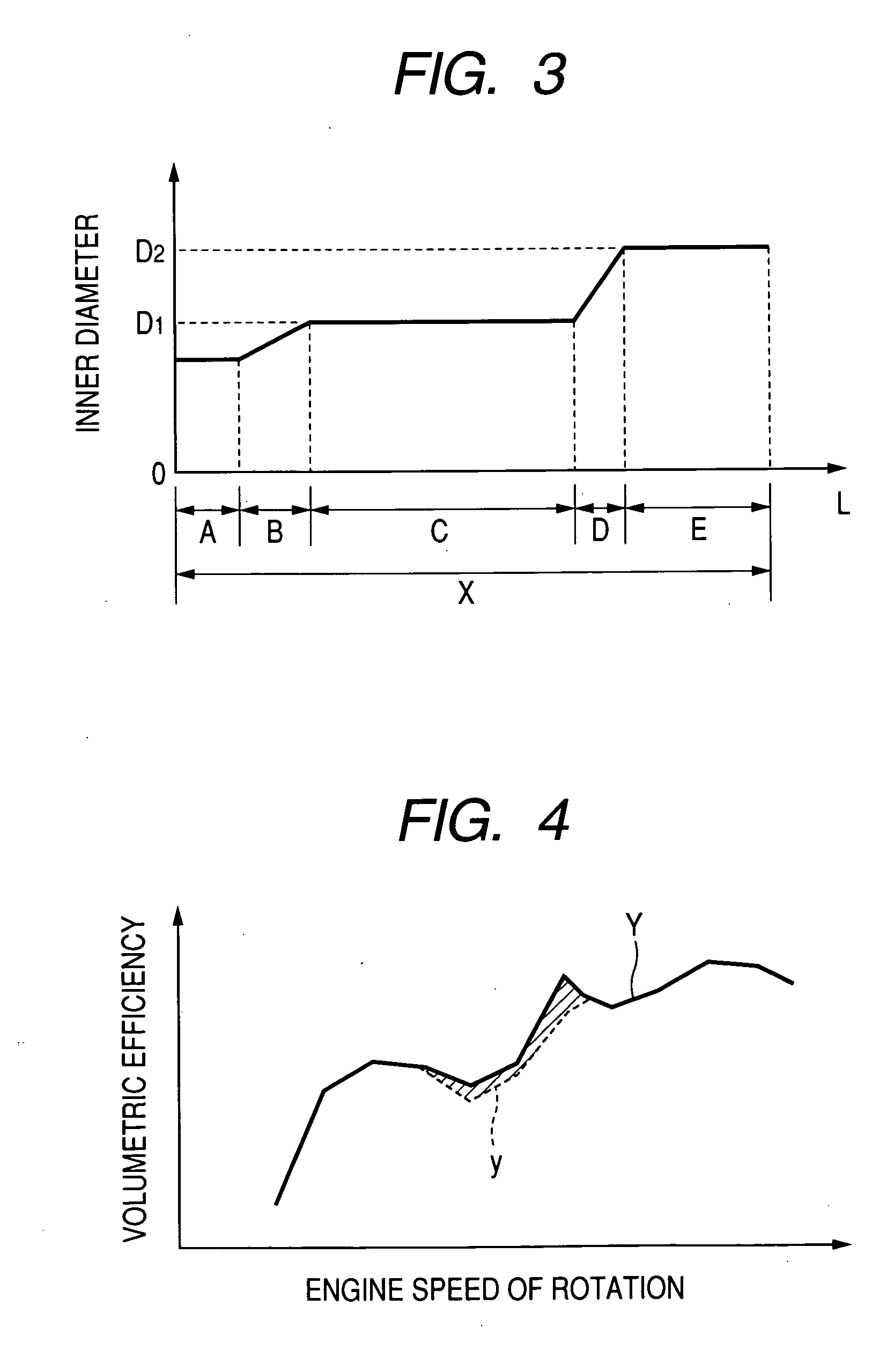
[0025] The branch pipe 11 has an opening 4 on the intake port 2 with an inner diameter almost equal to that of the intake port 2. Successively from the cylinder head 1 to the surge tank 5, the branch pipe 11 includes: portion “a” of the interval length A in which the inner diameter is kept equal to the inner diameter of the intake port 2, or the interval length A in which the inner diameter is slightly larger than the inner diameter of the intake port 2; portion “b” of the interval length B extending from portion “a”, in which the inner diameter is gradually increased; portion “c” of the interval length C extending from portion “b”, in which th...


PUM


Abstract

In a branch pipe of an intake manifold, portion c in the central part is kept at relatively small constant inner diameter for an interval C, and portion e of which an end is connected to the surge tank is kept at relatively large constant inner diameter for an interval E, whereby the volumetric efficiency at the time of medium speed and high speed of engine is excellent.

Description

CROSS-REFERENCE TO RELATED APPLICATION [0001] This application incorporates by references the subject matter of Application NO. 2003-359914 filed in Japan on 20 Oct. 2003, on which a priority claim is based under 35 U.S.C §119(a). BACKGROUND OF THE INVENTION [0002] 1. Field of the Invention [0003] The present invention relates to an intake manifold for an engine, and more particularly to a structure of a branch pipe thereof. [0004] 2. Description of the Related Art [0005] Conventionally, in an intake manifold for an engine, each branch pipe 3 connected to an intake port 2 of a cylinder head 1 has an opening 4 on the intake port 2 which has an inner diameter almost equal to that of the intake port 2. The inner diameter of the branch pipe 3 gradually increases toward the other opening 6 connected to a surge tank 5, as illustrated in FIG. 5. The intake air amount of cylinder in the engine or volumetric efficiency is affected by the length and inner diameter of the branch pipe 3. [0006]...

Claims


Application Information

Patent Timeline
IPC IPC(8): F02B27/00F02M35/10F02M35/104
CPCF02M35/10072F02M35/10111F02B27/006F02M35/112Y02T10/146F02M35/10118Y02T10/12
Inventor YAKABE, YOSHINORIITO, ATSUHITO
Owner MITSUBISHI MOTORS CORP
Why Eureka
Try Eureka