
Pushing handle for a shopping trolley

A technology of trolleys and push handles, applied in the direction of trolleys, multi-axis trolleys, trolley accessories, etc., which can solve the troublesome problems of handling smartphones

Inactive Publication Date: 2014-06-11
霍斯特松嫩多费尔 +1
View PDF16 Cites 4 Cited by
  • Summary
  • Abstract
  • Description
  • Claims
  • Application Information

AI Technical Summary

Problems solved by technology

[0008] However, handling a smartphone while shopping is a bit of a hassle due to frequent interruptions

Method used


Image

  • Pushing handle for a shopping trolley
  • Pushing handle for a shopping trolley
  • Pushing handle for a shopping trolley

Examples


Embodiment Construction

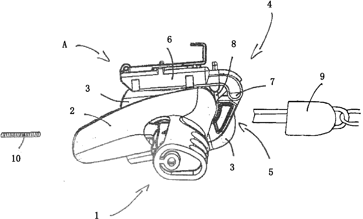
[0041] figure 1 Shown is a push handle 1 comprising an advertising display screen 2 and a deposit lock 3 substantially hidden behind the advertising display screen 2 . On the push handle 1 , a holder 4 for a smartphone is arranged at the same level as the deposit lock 3 . The holder 4 is connected, for example screwed, to the push handle 1 on both sides of the lock hole 5 . The mounting part 6 of the holder 4 is pivotally connected with the push handle 1 via a pivot joint 7 arranged above the deposit lock hole 5 .

[0042] exist figure 1 In the home position A shown, the mounting part 6 rests on the push handle 1 , or more precisely on the top of the deposit lock 3 . In the original position A, the guard 8 held on the mount 5 exposes the deposit lock hole 5, so that after pushing the deposit 10 into the deposit lock 3, the deposit key 9 can be removed and inserted again. With the deposit key 9 inserted, the mounting is blocked in the original position A, since the key head...


PUM


Abstract

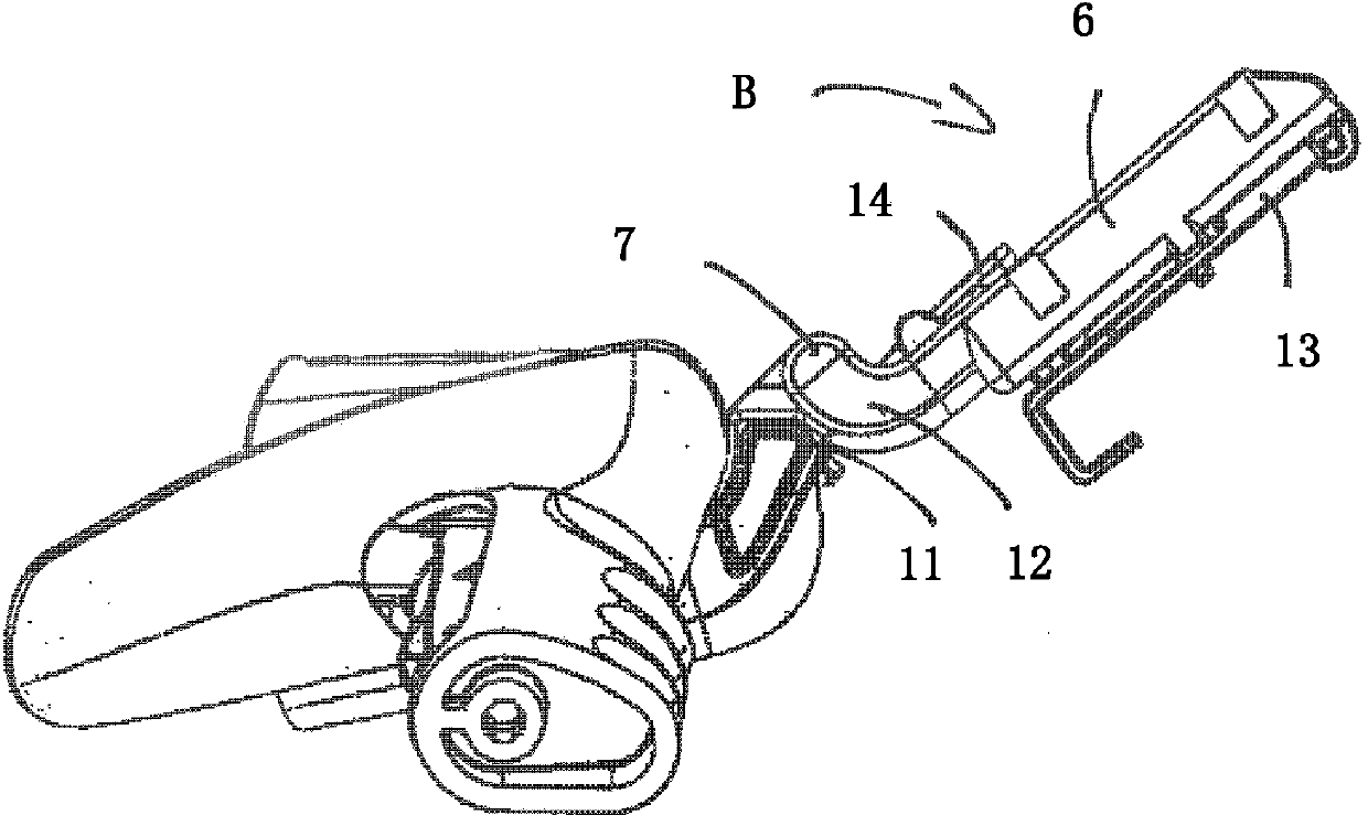
A pushing handle (1) for a shopping trolley, wherein the pushing handle (1) has a holder (4) for a mobile telecommunications terminal (16), in particular a smart phone, wherein the holder (4) comprises a receptacle (6) for the telecommunications terminal (18) and a rotary joint (7) by means of which the receptacle (6) is pivotable between a rest position (A) bearing against the pushing handle (1) and a holding position (B) protruding from the pushing handle (1).

Description

technical field [0001] The invention relates to a push handle for a shopping trolley and an anti-theft alarm system composed of the push handle according to the invention and a mobile communication terminal. Background technique [0002] Push handles for shopping trolleys have long outgrown the tasks for which they were originally designed. A simple stick with which to push a trolley through a store has become a functional carrier that must meet various requirements. Modern push handles are generally ergonomically shaped, often have a deposit lock, and often include advertising displays. [0003] Sometimes, push handles for shopping trolleys also include holders adapted to carry additional functional components on the push handle. Thus, GB2393526 shows a magnifying glass held on a push handle by a gooseneck. The gooseneck is extremely flexible, allowing the magnifying glass to be held in any desired position. However, such holders require a lot of space and are therefore...

Claims


Application Information

Patent Timeline
Patent Type & Authority Applications(China)
IPC IPC(8): B62B3/14B62B5/06
CPCB62B3/1428B62B5/06B62B3/1424H04M1/04B62B3/00B62B3/14B62B5/00B62B3/1472G08B13/22
Inventor 霍斯特·松嫩多费尔弗朗茨·维特
Owner 霍斯特松嫩多费尔
Learn More