Automatic bar feeder

An automatic feeding and bar material technology, which is applied in metal processing and other directions, can solve the problems of long overall structure of the feeding mechanism, inconvenient transportation and handling, and large space occupied by the machine, and achieve the effect of small machine occupation, simple structure, and convenient feeding

Active Publication Date: 2014-06-18
宁波华升数控车床有限公司
View PDF6 Cites 13 Cited by
  • Summary
  • Abstract
  • Description
  • Claims
  • Application Information

AI Technical Summary

Problems solved by technology

[0004] In the above-mentioned feeding mechanism, the ejector rod is located behind the bar, and the cylinder drives the ejector rod forward to push the bar into the lathe spindle for processing. This structure can only be used for feeding short bars. When the bar is longer, it will The overall structure of the feeding mechanism is very long, resulting in a complex structure, inconvenient transportation and handling, and takes up a lot of space

Method used


Image

  • Automatic bar feeder
  • Automatic bar feeder

Examples


Embodiment Construction

[0018] The present invention will be further described in detail below in conjunction with the accompanying drawings and embodiments.

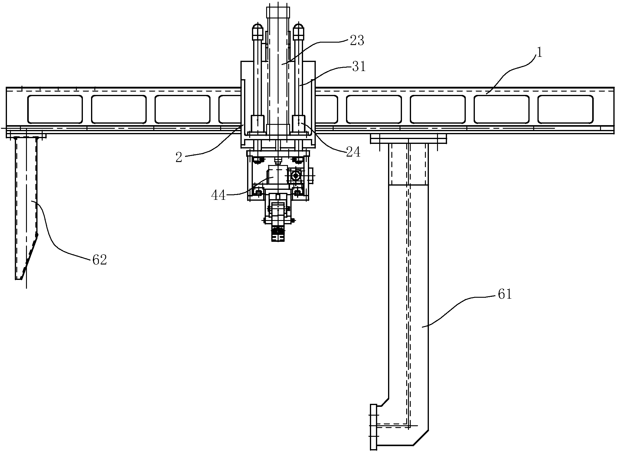
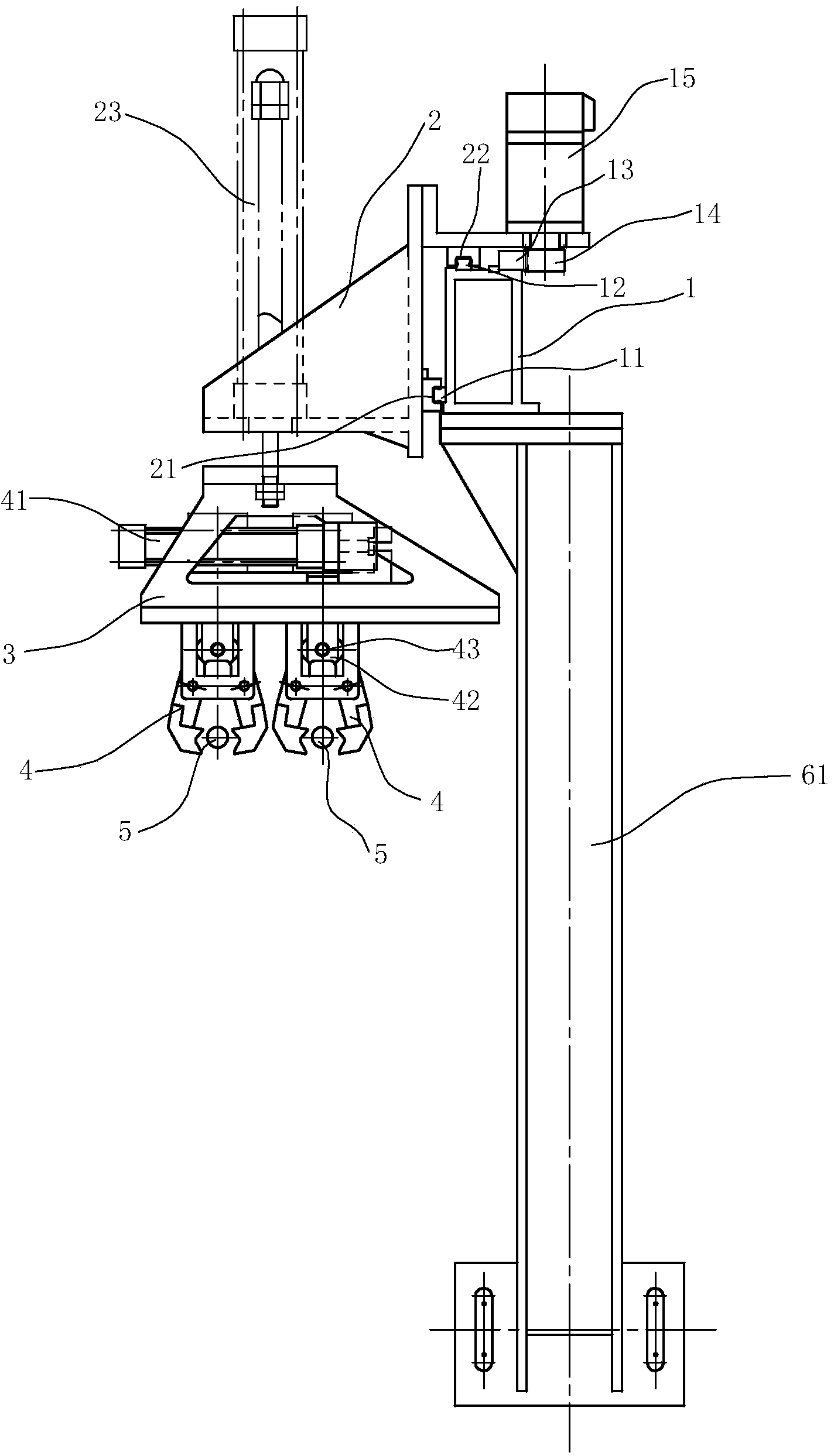
[0019] see figure 1 with figure 2 , a bar automatic feeding machine, including a beam 1, and a slide plate 2 that can slide along the beam 1. Slider 2 and crossbeam 1 sliding fit: the rear side of the slideboard 2 is located in front of the front side of the crossbeam 1, and the rear side of the skateboard 2 is provided with a first chute 21, which cooperates with the first crossbeam guide rail 11 on the front side of the crossbeam 1; The top surface is above the top surface of the crossbeam 1, and the top surface of the slide plate 2 is provided with a second slide groove 22, which cooperates with the second crossbeam guide rail 12 on the top surface of the crossbeam 1, thereby realizing the sliding fit of the crossbeam 1 and the slide plate 2. Those skilled in the art can easily imagine that the above two beam guide rails can also be arra...


PUM


Abstract

The invention discloses an automatic bar feeder. The automatic bar feeder is characterized in that the automatic bar feeder comprises a cross beam, a sliding plate and a mechanical arm support, wherein the sliding plate is arranged on the cross beam and capable of horizontally moving in the length direction of the cross beam, the mechanical arm support is arranged below the sliding plate and capable of vertically moving relative to the sliding plate, the mechanical arm support is provided with clamping claws which can move horizontally relative to the mechanical arm support in the direction perpendicular to the length direction of the cross beam, so three-axis movement of the clamping claws can be achieved. The three-axis movement of the clamping claws can be achieved through the cross beam, the sliding plate sliding horizontally relative to the cross beam and the mechanical arm support vertically moving relative to the sliding plate, and the automatic bar feeder is simple in structure, convenient to feed and small in occupied space; through the clamping claws capable of moving independently, the two clamping claws can be used for feeding bars to be processed and discharging processed bars at the same time, and the efficiency of the feeder can be improved.

Description

technical field [0001] The invention relates to a feeder, in particular to a feeder for automatically conveying bars. Background technique [0002] The lathe is an indispensable parts processing equipment in the entire machinery industry. During the process of processing parts on the lathe, it is usually necessary to put the workpiece from the front of the workpiece chuck of the lathe through manual operation, and then manually remove it from the workpiece chuck after processing. This method of manual feeding is labor-intensive, low in efficacy, and has great potential safety hazards, and may affect the processing quality due to differences in manual pushing positions and strengths. [0003] With the continuous development of modern society and the continuous progress of science and technology, as well as the increasing shortage of technical human resources and the increase of labor costs, the requirements for the degree of automation of lathes are getting higher and higher,...

Claims


Application Information

Patent Timeline
Patent Type & Authority Applications(China)
IPC IPC(8): B23B15/00
CPCB23Q7/042
Inventor 应圣平
Owner 宁波华升数控车床有限公司
Why Eureka
Try Eureka