Automobile machining board laser welding robot

A technology for laser welding and processing plates, applied in laser welding equipment, welding equipment, metal processing equipment, etc., to achieve the effect of improving welding efficiency, high degree of automation, and increasing contact area

Active Publication Date: 2019-09-17
昆山高科创志机器人自动化有限公司
View PDF7 Cites 6 Cited by
  • Summary
  • Abstract
  • Description
  • Claims
  • Application Information

AI Technical Summary

Problems solved by technology

[0006] The purpose of the present invention is to provide a laser welding robot for automobile processing panels, which aims to solve the problem in the prior art that the workpiece needs to be turned over manually to achieve double-sided welding when the workpiece is welded on both sides, thereby improving welding efficiency

Method used


Image

  • Automobile machining board laser welding robot
  • Automobile machining board laser welding robot
  • Automobile machining board laser welding robot

Examples


Embodiment 1

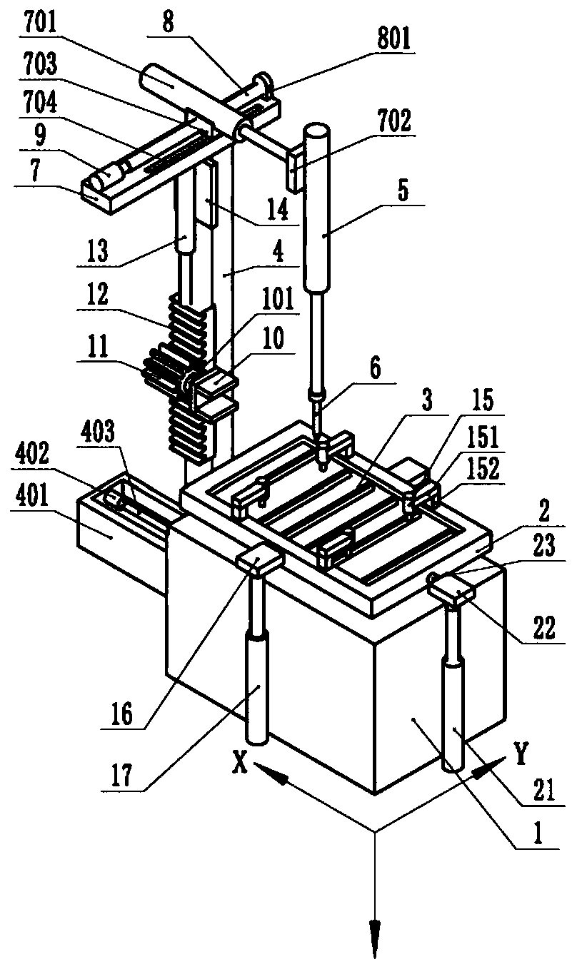
[0040] The embodiment is basically as attached figure 1 Shown: the laser welding robot for the automobile processing plate, including a workbench 1, a placement frame 2 is placed on the upper surface of the workbench 1, and the shape of the placement frame 2 can be set according to the shape of the actual workpiece to be welded. In this embodiment, the placement frame 2 The shape is cuboid, and the top and bottom ends of the placement frame 2 are open, so that the placement frame 2 is a frame structure. There are several poles 3 fixedly connected to the opposite sides of the placement frame 2. In this embodiment, the poles 3 are welded to both sides of the placement frame 2. The two adjacent poles 3 are parallel to each other, and the distance between the two adjacent poles 3 is There are gaps in between.

[0041] The workbench 1 is provided with a welding mechanism, an overturning mechanism and a pressing mechanism. The welding mechanism includes a fixed frame 4, a lifting ...

Embodiment 2

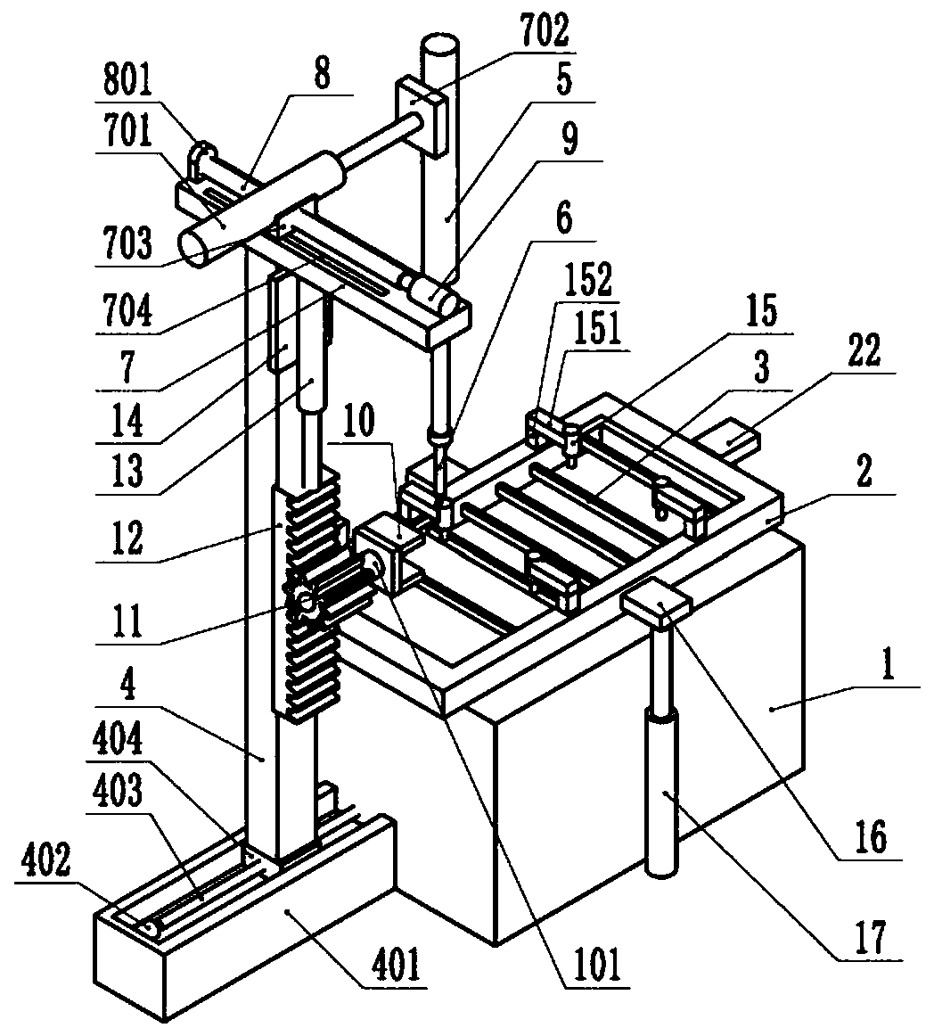
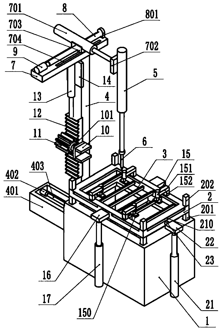
[0059] Such as image 3 , Figure 4 , Figure 5 and Figure 6 As shown, the difference between the laser welding robot for automobile processing plate and the first embodiment is that the inside of the workbench 1 is a hollow structure, and the top of the workbench 1 is open.

[0060] A positioning cylinder 18 is arranged in the workbench 1 , and the output end of the positioning cylinder 18 is arranged facing the direction of the placing frame 2 . The bottom of the positioning cylinder 18 is fixedly connected with the bottom of the workbench 1 by bolts. The output end of the positioning cylinder 18 is fixedly connected with a partition 19 by bolts, and the width of the partition 19 is the distance between the welds of the two workpieces in the actual processing. The partition 19 is arranged parallel to the poles 3 and is located between two adjacent poles 3 , so that the poles 3 do not obstruct the rising and falling of the partition 19 . In this implementation, the posi...


PUM


Abstract

The invention belongs to the technical field of panel welding instruments, and particularly discloses an automobile machining board laser welding robot. A workbench is included. A containing frame is placed on the workbench and internally provided with a plurality of support rods. The support rods are fixedly connected with the two opposite sides of the containing frame. A welding mechanism, an overturning mechanism and a pressing mechanism are arranged on the workbench. The welding mechanism comprises a fixing frame, a lifting assembly and a welding head. The welding head is fixed to the lifting assembly, the lifting assembly is used for driving the welding head to move towards the Z axis, and the fixing frame is provided with a first drive unit driving the lifting assembly to move towards the X axis, and a second drive unit driving the lifting assembly to move towards the Y axis. The overturning mechanism comprises a clamping claw and a rotation assembly, wherein the clamping claw is used for clamping the containing frame, the rotation assembly is located on one side of the fixing frame, the clamping claw is fixedly connected with the rotation assembly, and the rotation assembly is used for driving the clamping claw to overturn. The pressing mechanism is used for pressing a workpiece. The automobile machining board laser welding robot can automatically overturn the workpiece, and accordingly double-face welding can be conducted on the workpiece.

Description

technical field [0001] The application of the present invention belongs to the technical field of plate welding equipment, and specifically discloses a laser welding robot for automobile processing plates. Background technique [0002] Welding is the process of joining metal parts using various fusible alloys. The current welding methods include manual welding and machine welding. Manual welding is time-consuming and laborious, the production efficiency is low, the welding quality is difficult to meet the welding standard, and there are great safety hazards. At present, most projects use machine welding, and welding robots in machine welding are favored by most factories due to their high degree of automation. [0003] A welding robot is an industrial robot engaged in welding. The industrial robot is used in the field of industrial automation. It is a multi-purpose, reprogrammable automatic control operation machine, usually with three or more programmable axes, so that the...

Claims


Application Information

Patent Timeline
Patent Type & Authority Applications(China)
IPC IPC(8): B23K26/21B23K26/70
CPCB23K26/21B23K26/702
Inventor 孙兵涛
Owner 昆山高科创志机器人自动化有限公司
Why Eureka
Try Eureka