AI technical title is built by Patsnap AI team. It summarizes the technical point description of the patent document.
A waveform display and waveform technology, applied in digital variable/waveform display, measurement devices, instruments, etc., can solve the problem of overlapping waveforms and achieve the effect of direct waveform observation.
Active Publication Date: 2014-06-18
RIGOL
View PDF11 Cites 1 Cited by
Summary
Abstract
Description
Claims
Application Information
AI Technical Summary
This helps you quickly interpret patents by identifying the three key elements:
Problems solved by technology
Method used
Benefits of technology
Problems solved by technology
[0004] The main purpose of the embodiments of the present invention is to provide a waveform display method and a display device to solve the defect that the waveforms overlap each other when multiple waveforms are displayed in the same display area in the existing waveform display device
Method used
Image
Click on the blue label to locate the original text in one second.
Reading with bidirectional positioning of images and text.
Examples
Embodiment 1
[0038] This embodiment provides a waveform display method, including:
[0039] Dividing the screen into at least one display area, outputting at most one waveform display data to each display area and displaying it;
[0040] When the waveform shift indication information is received, the following processing is performed:
[0041] determining the pre-shifted waveform, the original display area and the pre-shifted-in display area according to the waveform shift indication information;
[0042] stop outputting the display data of the pre-shift waveform to the original display area;
[0043] When it is determined that no waveform is currently displayed in the pre-shifted display area, the display data of the pre-shifted waveform is directly output to the pre-shifted display area for display; when it is determined that the pre-shifted display area displays the occupied waveform, the The display data of the occupied waveform is output to other display areas outside the pre-shift ...
Embodiment 2
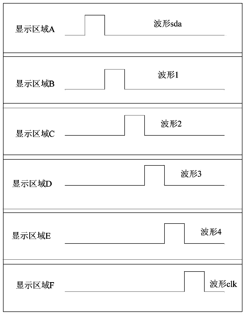
[0092] This embodiment provides a waveform display device, such as Figure 11 As shown, the device includes:
[0093] an area division module 111, configured to divide the screen into at least one display area;
[0094] A data output module 112, configured to output waveform display data to the display area;
[0095] an output control module 113, configured to control the data output module 112 to output at most one waveform display data to each display area;
[0096] An information receiving module 114, configured to receive waveform shift indication information;
[0097] An information analysis module 115, configured to determine the pre-shifted waveform, the original display area and the pre-shifted-in display area according to the waveform shift indication information;
[0098] The shift control module 116 is used to control the data output module 112 to stop outputting the display data of the pre-shift waveform to the original display area, and when it is determined th...
PUM
Abstract
The invention provides a waveform display method and display device. The method includes: segmenting a screen into at least one display area, and outputting and displaying display data of at most one waveform to each display area; when a waveform shift indication information is received, executing the following processing processes: a pre-shift waveform, an original display area and a pre-shift-in display area are determined according to waveform shift indicating information; display data of the pre-shift waveform are stopped from being output to the original display area; when the pre-shift-in display area is determined not to display a waveform at present, the display data of the pre-shift waveform is directly output to the pre-shift-in display area for display; when the pre-shift-in display area is determined to display an occupied waveform, display data of the occupied waveform are output to another display area outside the pre-shift-in display area, and the display data of the pre-shift waveform are output to the pre-shift-in display area for display. The waveform display method provides a relatively direct observation effect for a user, and omits the trouble of frequent shift operation for waveform observation.
Description
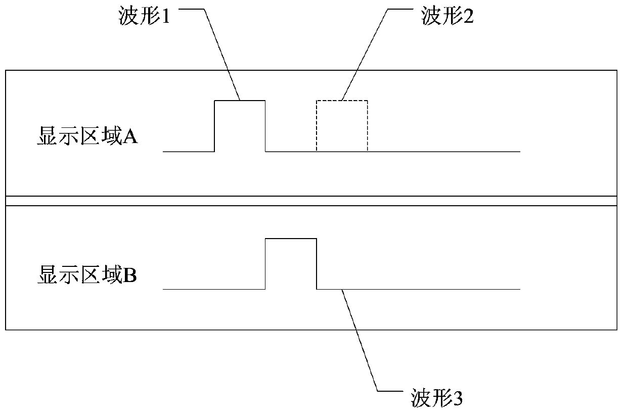
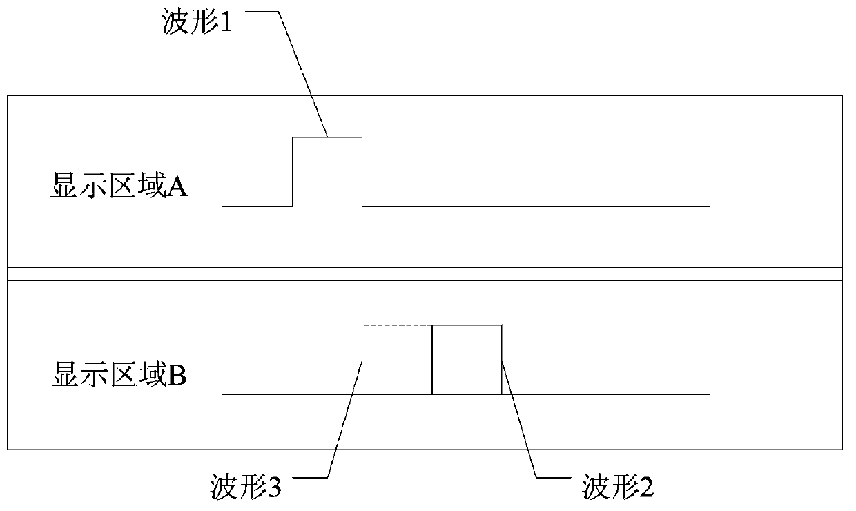
technical field [0001] The present invention relates to the technical field of waveform display, in particular to a waveform shift display method and a display device. Background technique [0002] Common waveform display devices such as oscilloscopes can usually display the waveforms of multiple acquisition signals at the same time. The display features are usually: the device screen is divided into multiple display areas, and the waveforms are displayed in these display areas. Multiple channels can be displayed in the same display area. These waveforms cover each other, and the lower waveform can only be displayed after the upper waveform is shifted; figure 1 As shown, waveform 1 in display area A covers waveform 2. To observe waveform 2, waveform 1 needs to be shifted, as shown in figure 2 As shown, when waveform 1 is moved from display area A to display area B, waveform 2 can only be observed in display area A, but at the same time, waveform 3 originally displayed in d...
Claims
Application Information
Patent Timeline
Application Date:The date an application was filed.
Publication Date:The date a patent or application was officially published.
First Publication Date:The earliest publication date of a patent with the same application number.
Issue Date:Publication date of the patent grant document.
PCT Entry Date:The Entry date of PCT National Phase.
Estimated Expiry Date:The statutory expiry date of a patent right according to the Patent Law, and it is the longest term of protection that the patent right can achieve without the termination of the patent right due to other reasons(Term extension factor has been taken into account ).
Invalid Date:Actual expiry date is based on effective date or publication date of legal transaction data of invalid patent.

