Brushless DC motor

A brushless DC motor and rotor technology, applied in electric components, electrical components, electromechanical devices, etc., can solve the problems of large difference in sine wave waveform, large motor vibration, and many back-EMF harmonics, and achieve small back-EMF harmonics. , not easy to move, stable operation effect

Pending Publication Date: 2019-01-18
浙江方远四福机电有限公司
View PDF8 Cites 0 Cited by
  • Summary
  • Abstract
  • Description
  • Claims
  • Application Information

AI Technical Summary

Problems solved by technology

However, during the rotation of the motor, the back EMF waveform generated by the motor is as follows: figure 2 As shown, there is a large difference from the sine wave waveform; and the motor produces more back EMF harmonics, such as image 3 As shown, that is to say, the motor vibrates greatly during operation

Method used


Image

  • Brushless DC motor
  • Brushless DC motor
  • Brushless DC motor

Examples


Embodiment Construction

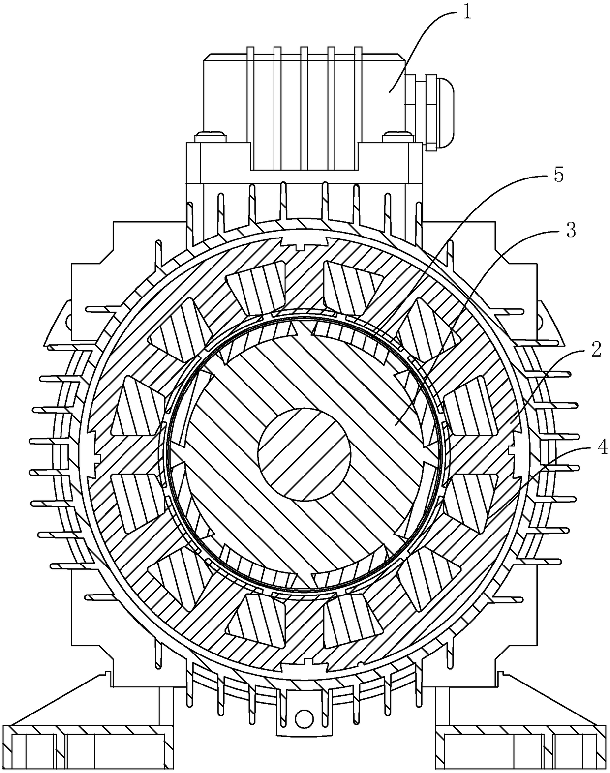
[0034] A DC brushless motor such as Figure 4 , Figure 5 As shown, it includes a housing 1 , a stator 2 coaxially embedded in the housing 1 , and a rotor 3 coaxially connected to the housing 1 for rotation.

[0035] Such as Figure 5 As shown, in this embodiment, the diameter of the outer ring of the stator 2 is 130 mm, and the diameter of the inner ring of the stator 2 is 84 mm. The inner wall of the stator 2 close to the rotor 3 is provided with 12 winding slots 4 , and the 12 winding slots 4 are evenly distributed around the axis of the stator 2 . Each winding slot 4 extends axially along the stator 2 , and two ends of the winding slot 4 pass through the two ends of the stator 2 respectively. Each winding slot 4 shrinks toward one side of the stator 2 axis. In this embodiment, the depth of the winding groove 4 is 14.5mm. The inner slot walls of the winding slot 4 are rounded, and the radius of the rounded corners is 1mm. An abutment block 7 is integrally formed on th...


PUM


Abstract

The invention discloses a direct current brushless motor, which relates to the technical field of the motor. The technical scheme includes a housing, a stator arranged in the housing and a rotor rotatably connected with the housing. The end face of the stator facing the rotor is provided with a winding groove, and the winding groove extends along the stator axis and penetrates both ends of the stator. The number of the winding grooves is 12, and the 12 winding grooves are arranged in a circumferential array with the stator axis as the center; The outer wall of the rotor is provided with a placing groove for placing the magnetic steel, and the placing groove extends along the axial direction of the rotor and penetrates both ends of the rotor; Characterized in that the number of the placinggrooves is 10, and the 10 placing grooves are arranged in a circumferential array with the rotor axis as the center. The rotor is provided with 10 slots arranged in a circumferential array around therotor axis, so that the back EMF is closer to sinusoidal, the back EMF harmonics are smaller, and the operation of the motor is more stable.

Description

technical field [0001] The invention relates to the technical field of motors, in particular to a DC brushless motor. Background technique [0002] Existing brushless DC motors such as figure 1 As shown, it includes a housing 1 , a stator 2 disposed inside the housing 1 , and a rotor 3 rotatably connected to the housing 1 . A winding slot 4 is opened on the side wall of the stator 2 facing the rotor 3 , and the winding slot 4 extends along the axial direction of the stator 2 and penetrates both ends of the stator 2 . The number of winding slots 4 is 12, and the 12 winding slots 4 are distributed in a circular array around the axis of the stator 2 . The outer wall of the rotor 3 is provided with a placement slot 5 for placing the magnetic steel, and the placement slot 5 extends along the axis of the rotor 3 and penetrates both ends of the rotor 3 . The number of placement slots 5 is eight, and the eight placement slots 5 are distributed in a circular array around the axis ...

Claims


Application Information

Patent Timeline
Patent Type & Authority Applications(China)
IPC IPC(8): H02K1/16H02K1/27
CPCH02K1/165H02K1/276
Inventor 何斌艾朝军
Owner 浙江方远四福机电有限公司
Why Eureka
Try Eureka