
Cloud resource situation perception system structure

A context-aware and architectural technology, applied in the field of cloud computing and perception computing, can solve the problems of prolonged acquisition of cloud resources, uncertainty of service demand, inability to realize on-demand resource allocation, etc., to achieve efficient acquisition and use, Addressing the effects of effective sharing and full utilization

Inactive Publication Date: 2014-07-02
SUZHOU VOCATIONAL UNIV
View PDF2 Cites 6 Cited by
  • Summary
  • Abstract
  • Description
  • Claims
  • Application Information

AI Technical Summary

Problems solved by technology

However, (1) services are scattered and difficult to maintain
Decentralized management of data will cause data duplication and redundancy
(2) The on-demand allocation of resources cannot be realized
Since the service is relatively independent, and the demand for the service is uncertain, there may even be untimely and uneven service response
(3) In most cases, the load is very low, but a lot of power is wasted
[0006] Through analysis, solution (1) mainly focuses on the establishment and reasoning of the situation model, and the architecture is not based on the computing method of the Internet, and does not consider the on-demand allocation of cloud resources and information; solution (2) when the environment, task or situation changes , resource mapping and effective use of cloud resources can only be performed on the premise of manual intervention by users; (3) The framework includes connection management, component management, service discovery, message processing, user interface and context storage structure are too complex, cloud resource acquisition delay Longer, less efficient and less accurate
These three schemes fail to sense the dynamic changes of the internal / external environment, and with such changes, perform static adjustments and dynamic evolutions according to functional indicators, performance indicators, or reliability indicators, so that the system has as high a user experience as possible. satisfaction

Method used


Image

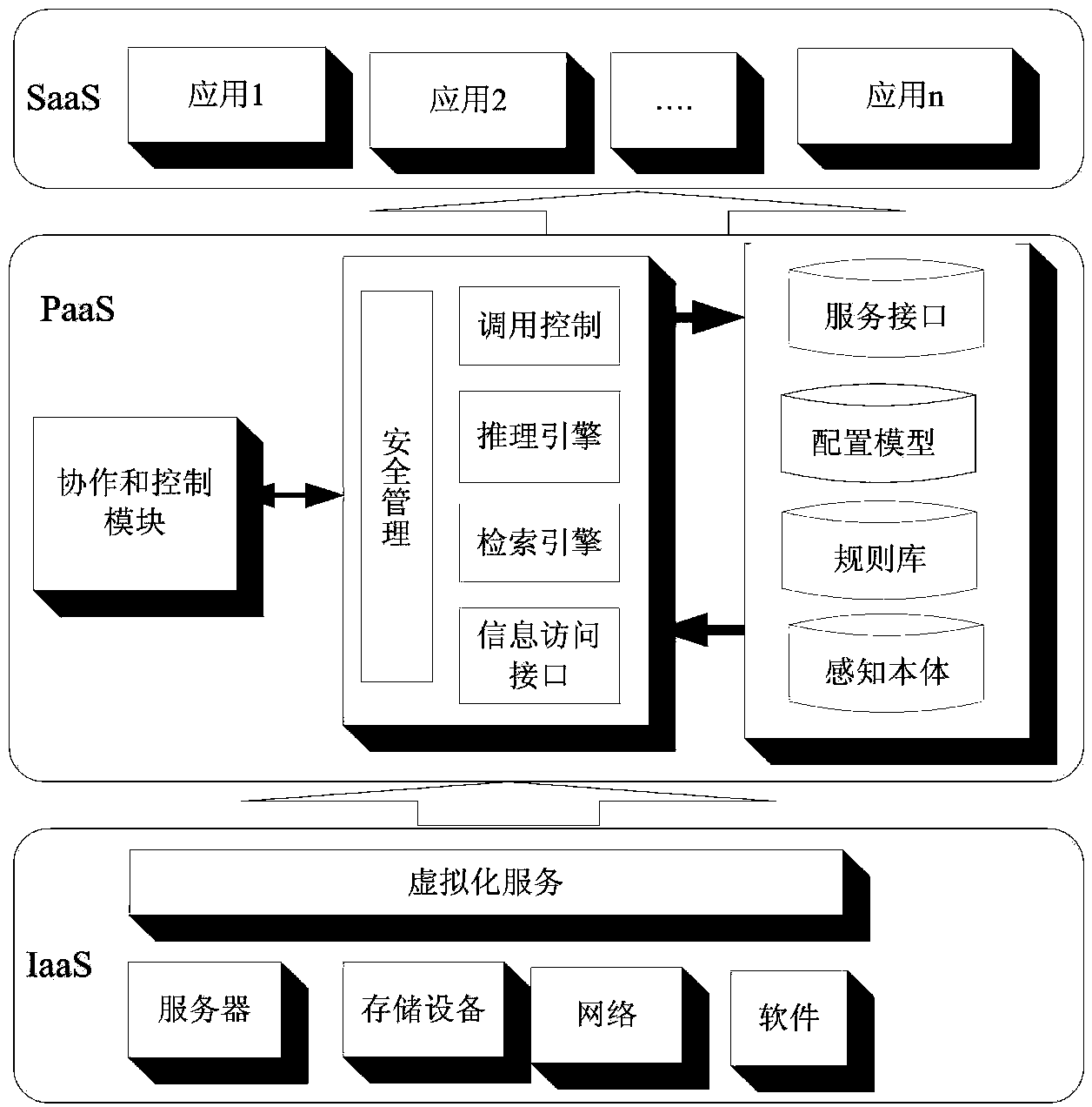
  • Cloud resource situation perception system structure
  • Cloud resource situation perception system structure

Examples


Embodiment Construction

[0021] The preferred embodiments of the present invention will be described in detail below in conjunction with the accompanying drawings, so that the advantages and features of the present invention can be more easily understood by those skilled in the art, so as to define the protection scope of the present invention more clearly.

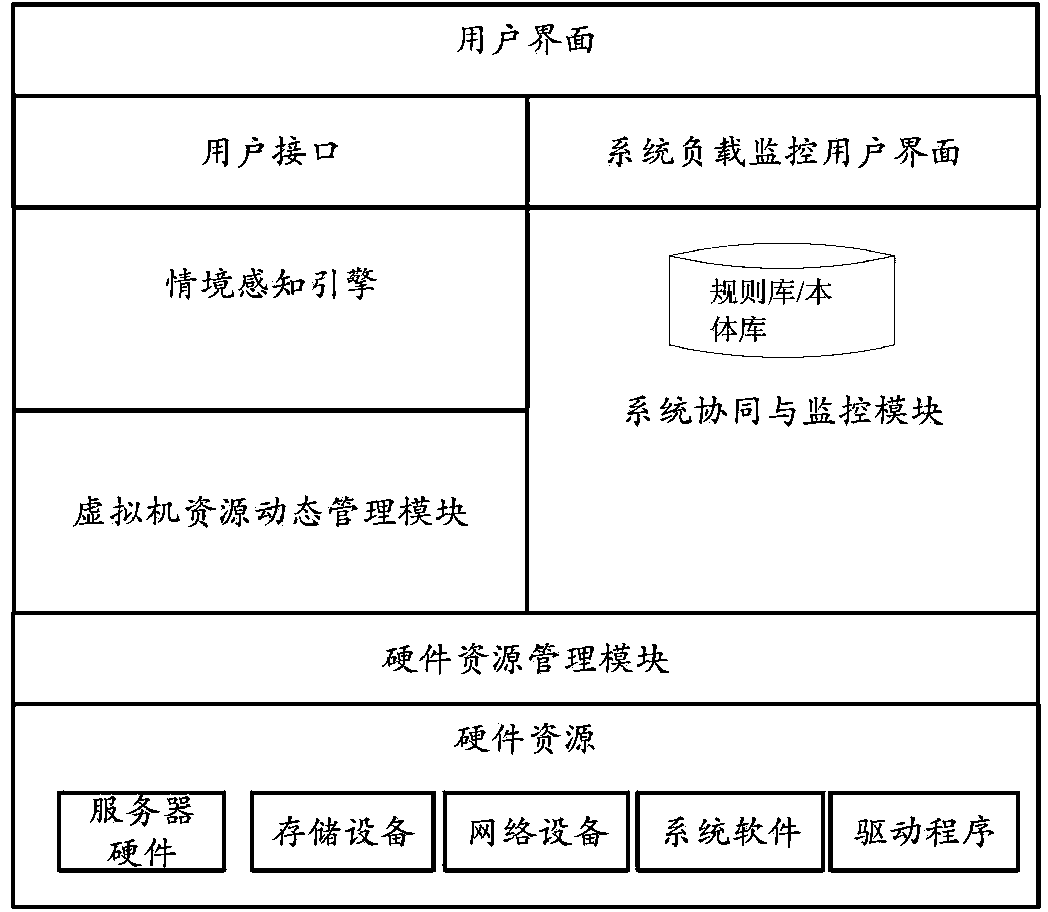
[0022] Such as figure 1 As shown, the system design or architecture of the cloud resource context awareness architecture of the present invention includes functional modules such as firmware, middleware, and components. Combined with the specific implementation technology, the realization of the supporting environment is divided into five aspects: the operation of the context ontology, the selection and access of services, the subscription and publication of the context, the autonomous components, and the server access.

[0023] see figure 2 , the embodiment of the present invention includes:

[0024] The architecture or system of the present ...


PUM


Abstract

The invention discloses a cloud resource situation perception system structure. The cloud resource situation perception system structure comprises an IaaS layer, a PaaS layer and a SaaS layer. The IaaS layer comprises various units for directly providing situational information, and the situation information may come from hardware equipment or software services or people. The PaaS layer comprises a situation perception engine, a storage tank and a Collaboration Module. Situation information models, inference rules, configuration models and business service interfaces used by the situation perception engine are stored in the storage tank. The SaaS layer comprises various business services provided for users, wherein the business services can be Webservice or can also be entity services in real life. By means of the cloud resource situation perception system structure, cloud resources comprising calculating, storing, calling, inferring, safety, querying and other function modules at the service layer can be distributed according to needs.

Description

technical field [0001] The invention relates to the fields of cloud computing and perceptual computing. Background technique [0002] In the cloud computing environment, all resources and applications will be integrated on the "cloud", and each learner can use these resources and applications to freely create a virtual community, build their own virtual learning environment, and share common learning goals Collaborative learning with other learners. However, (1) services are scattered and difficult to maintain. Decentralized management of data will result in duplication and redundancy of data. (2) The on-demand allocation of resources cannot be realized. Since the service is relatively independent and the demand for the service is uncertain, there may even be untimely and uneven service responses. (3) In most cases, the load is very low, but a large amount of electric energy is wasted. Therefore, a solution needs to be found. Currently, there are three specific solutio...

Claims


Application Information

Patent Timeline
Patent Type & Authority Applications(China)
IPC IPC(8): H04L29/08
Inventor 刘文芝刘昭斌曾海
Owner SUZHOU VOCATIONAL UNIV
Learn More