Floor heating control method

A control method and floor heating technology, applied in the field of floor heating control, can solve problems such as poor energy saving, overheating or overcooling of room temperature, energy waste of floor heating system, etc., so as to avoid overheating or overcooling of water supply temperature Effect

Active Publication Date: 2014-07-09
GREE ELECTRIC APPLIANCES INC
View PDF7 Cites 12 Cited by
  • Summary
  • Abstract
  • Description
  • Claims
  • Application Information

AI Technical Summary

Problems solved by technology

[0003] Disadvantages of the prior art: the floor heating in the prior art generally relies solely on the method of controlling the temperature of the floor heating water supply to adjust the room temperature. Due to the existence of thermal inertia and the influence of the ambient temperature, there is unnecessary waste of energy in the floor heating system, and the energy saving is relatively low. Poor, and using the floor heating system in the prior art, the room temperature is prone to overheating or overcooling

Method used


Image

  • Floor heating control method

Examples


Embodiment Construction

[0018] It should be noted that, in the case of no conflict, the embodiments in the present application and the features in the embodiments can be combined with each other. The present invention will be described in detail below with reference to the accompanying drawings and examples.

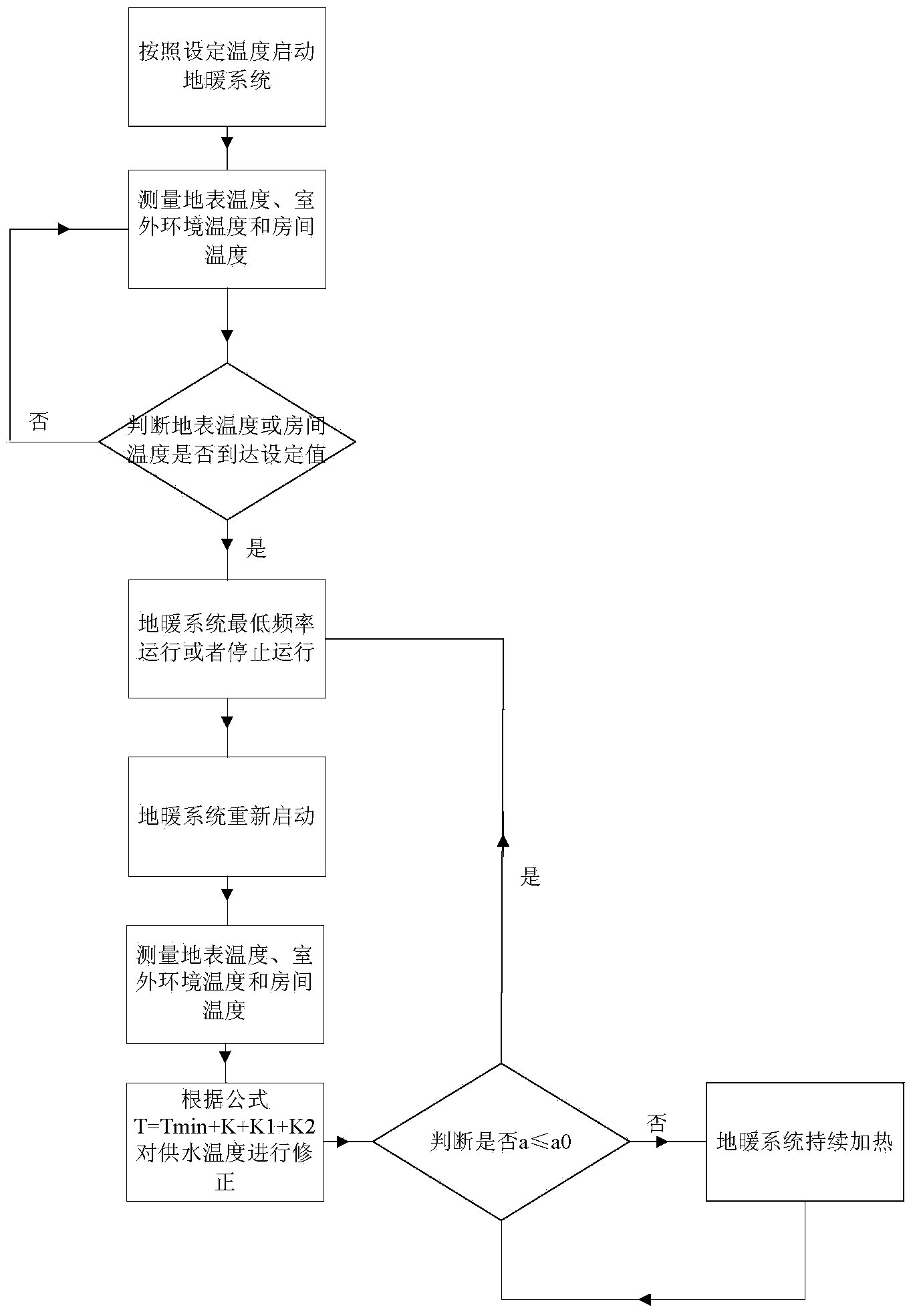
[0019] In the prior art, due to the thermal inertia of the floor, when the floor heating system starts to heat for the first time, the floor temperature will not rise at the beginning of energy storage for the floor. After a period of time, the floor energy storage ends and the floor surface temperature begins to rise. . After reducing the water supply temperature or shutting down, due to the thermal inertia of the floor, its surface temperature will continue to rise for a period of time, which will easily cause the room temperature to be too cold or overheated, and at the same time, it is not easy to save energy.

[0020] In view of the above problems, the present invention provides a floor h...


PUM


Abstract

The invention discloses a floor heating control method. The floor heating control method includes steps of S10, operating a floor heating system according to a set water supply temperature Tw when the floor heating system is firstly operated; S20, measuring a surface temperature Tf, an outdoor environment temperature T0 and a room temperature Te of a floor heating room; S30, operating the floor heating system in a standby state and recording a return water temperature when the surface temperature Tf reaches a set surface temperature Tf1 or the room temperature Te reaches a user set temperature Te1; S40, when the floor heating system is restarted, correcting the water supply temperature according to a formula T=Tmin+K+K1+K2, wherein the T refers to the water supply temperature, the Tmin refers to the minimum value of the set surface temperature Tf1 and the water return temperature, the K refers to a constant, the K1 refers to the corrected value of the outdoor environment temperature, and the K2 refers to the corrected value of the room temperature. By the floor heating control method, when operation parameters of the current floor heating system are compared with operation parameters of the previous floor heating system, the water supply temperature can be corrected by the formula T=Tmin+K+K1+K2 according to comparison results, and accordingly, too high or too low room temperature can be prevented.

Description

technical field [0001] The invention relates to a method for controlling floor heating. Background technique [0002] Floor heating is an extremely ideal heating method. It uses low-temperature hot water as a heat source, heats the floor through coils buried in the floor, and regulates the room temperature by means of radiation heat exchange and convection heat exchange. [0003] Disadvantages of the prior art: the floor heating in the prior art generally relies solely on the method of controlling the temperature of the floor heating water supply to adjust the room temperature. Due to the existence of thermal inertia and the influence of the ambient temperature, there is unnecessary waste of energy in the floor heating system, and the energy saving is relatively low. Poor, and using the floor heating system in the prior art, the room temperature is prone to overheating or overcooling. Contents of the invention [0004] The present invention aims to provide a floor heating...

Claims


Application Information

Patent Timeline
IPC IPC(8): F24D19/10
Inventor 欧阳光曹浩黄娟钟文朝
Owner GREE ELECTRIC APPLIANCES INC
Why Eureka
Try Eureka