Great saphenous vein drawing and peeling tunnel hemostat

A hemostat and tunnel technology, applied in the field of surgical supplies, can solve the problems of reduced operation efficiency, high manpower and energy, and high mental pressure, and achieve the effects of improving efficiency, relieving mental pressure, and reducing manpower and energy

Active Publication Date: 2014-07-16
莫经刚
View PDF6 Cites 3 Cited by
  • Summary
  • Abstract
  • Description
  • Claims
  • Application Information

AI Technical Summary

Problems solved by technology

However, this traditional saphenous vein stripping operation takes a long time, requires a lot of manpower and energy, and also puts a lot of mental pressure on the medical staff who hold down the saphenous vein for a long time, which also has a negative impact on the safety of the operation. A certain degree of influence, the efficiency of the operation is also reduced to a certain extent

Method used


Image

  • Great saphenous vein drawing and peeling tunnel hemostat
  • Great saphenous vein drawing and peeling tunnel hemostat
  • Great saphenous vein drawing and peeling tunnel hemostat

Examples


Embodiment 1

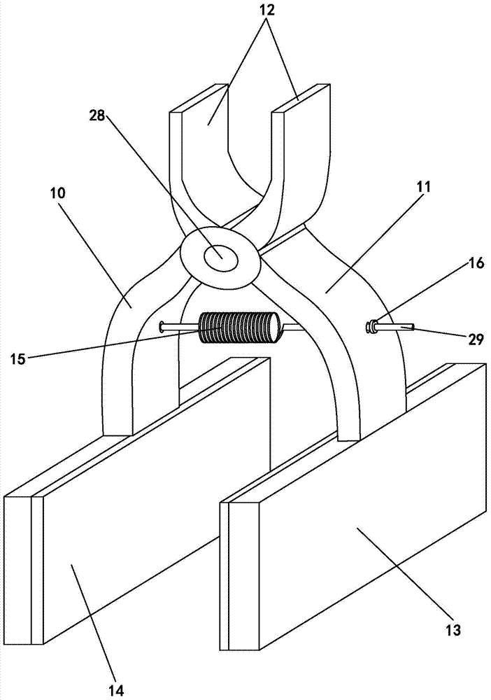
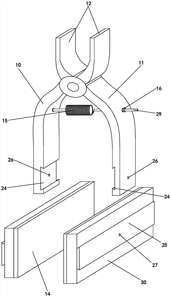
[0018] Embodiment one, such as figure 1 , figure 2 As shown, the tightness of the spring 15 can be adjusted as follows: the screw rod 29 at one end of the spring 15 and the other end of the screw rod 29 pass through the right clamp arm 11 or the left clamp arm 10 between the hinge shaft 28 and the clamping part 13 The through hole on the top is connected with the adjusting nut 16, that is, the spring 15 and the screw rod 29 are integrated, and the position of the adjusting nut 16 on the screw rod 29 can adjust the tightness of the spring 15. In this embodiment, if one end of the spring 15 is arranged on the left clip arm 10 between the hinge shaft 28 and the clamping part 13, then the other end of the spring 15 is arranged on one end of the screw rod 29, and the other end of the screw rod 29 passes through The through hole on the right clamp arm 11 between the hinge shaft 28 and the clamping part 13 is connected with the adjusting nut 16; and vice versa.

Embodiment 2

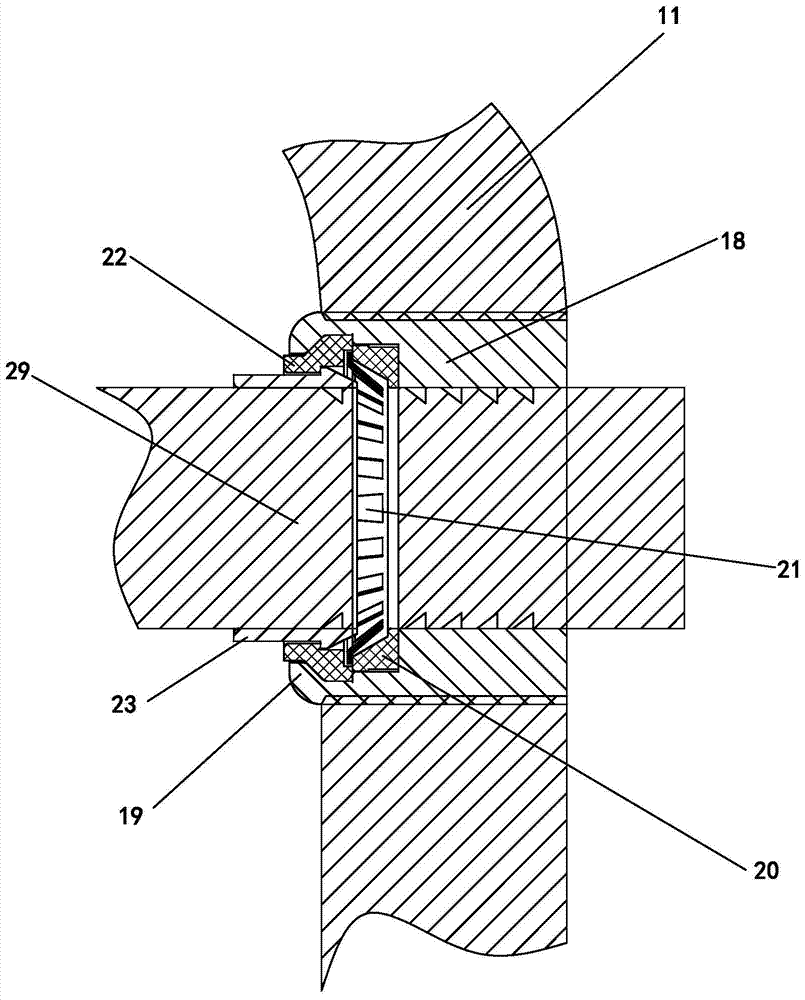
[0019] Embodiment 2, the tightness of the spring 15 can be adjusted as follows: one end of the spring 15 is arranged on the screw rod 29, and the screw rod 29 passes through and extends out of the right clamping arm 11 or the left clamping arm 11 between the hinge shaft 28 and the clamping part 13. One end of the through hole of the clamp arm 10 is provided with a plurality of ring-shaped inclined grooves 17, and the through hole of the right clamp arm 11 or the left clamp arm 10 is screwed with a clamping sleeve 18; the port of the clamping sleeve 18 is provided with Shrink mouth 19, clamping sleeve 19 is provided with elastic compression ring 20, clamping claw 21 is provided along its circumference on the clamping ring 20, and one side of claw 21 is provided with annular plastic shell 22, and the plastic shell The body 22 is clamped in the cavity between the constriction 19 and the compression ring 20 , and the unlocking sleeve 23 is clamped in the plastic shell 22 . In this...


PUM


Abstract

The invention relates to the technical field of surgical items, in particular to a great saphenous vein drawing and peeling tunnel hemostat. The great saphenous vein drawing and peeling tunnel hemostat comprises a left clamping arm and a right clamping arm, wherein the left clamping arm and the right clamping arm are crossed and are hinged to each other; the clamping arms on the upper portion of a hinged shaft form a handheld portion; lower portions of the left clamping arm and the right clamping arm on the lower portion of the hinged shaft are clamping portions; soft pads are respectively arranged on opposite inner side walls of the two clamping portions; one end of a spring is arranged on the left clamping arm or the right clamping arm between the hinged shaft and the clamping portions; the other end of the spring is arranged on the right clamping arm or the left clamping arm between the hinged shaft and the clamping portions; and the tightness of the spring can be adjusted. The great saphenous vein drawing and peeling tunnel hemostat has the advantages that in a great saphenous vein drawing and peeling surgery, labor and vigor which are required in the surgery are reduced, the mental stress of medical staff is greatly relieved, the safety of the surgery is improved, and the efficiency of the surgery is also improved obviously.

Description

technical field [0001] The invention relates to the technical field of surgical supplies, in particular to a great saphenous vein stripping tunnel hemostat. Background technique [0002] At present, in the traditional great saphenous vein stripping operation, it is necessary for a doctor or an assistant to help hold down the tunnel left by the patient's great saphenous vein stripping to compress the blood vessels in the tunnel to prevent bleeding in the tunnel, and to avoid bleeding in the tunnel after surgery. Hematoma formation. In order to avoid postoperative complications. However, this traditional saphenous vein stripping operation takes a long time, requires a lot of manpower and energy, and also puts a lot of mental pressure on the medical staff who hold down the saphenous vein for a long time, which also has a negative impact on the safety of the operation. To a certain extent, the efficiency of the operation is also reduced to a certain extent. Contents of the i...

Claims


Application Information

Patent Timeline
Patent Type & Authority Applications(China)
IPC IPC(8): A61B17/12
CPCA61B17/12A61B2017/12004
Inventor 莫经刚
Owner 莫经刚
Why Eureka
Try Eureka