breathable insole

A technology of insole and pad body, applied in insoles, footwear, clothing and other directions, can solve the problems of different heel friction, air circulation, feeling of foreign objects on the sole of the foot, etc., to simplify the manufacturing process and cost, simplify the cumbersome process, The effect of increasing comfort

Active Publication Date: 2016-08-17
黄市承 +1
View PDF7 Cites 0 Cited by
  • Summary
  • Abstract
  • Description
  • Claims
  • Application Information

AI Technical Summary

Problems solved by technology

The use of insoles like this with suction pipes, exhaust pipes and other conduits has the following restrictions: ① using soft conduits is easy to block due to compression; ② using hard conduits is easy to make the user's soles feel ③The directly exposed air cushion is easy to be worn out, and it is easy to cause uneven touch on the sole of the foot, and there may even be a problem of slippage due to different friction at the heel position; ④A single duct is used to squeeze air into the front of the sole of the foot , it is easy to cause the problem that air only circulates from a single path (between a single toe gap); ⑤The exposed air valve is easy to be damaged and blocked by foreign objects, and the round-shaped air valve is easy to cause discomfort when stepping on it; ⑥The airbag is equipped with elasticity Tissues or springs are likely to cause foot sports injuries after the aging of the wrapping, which needs to be improved
[0005] There are also insoles designed by advanced people, including airbags, inhalation areas, and exhaust areas. The exhaust areas are connected through the air intake. When the backlog of the air bag, the air generated by the backlog of the suction area can only be directed to the exhaust area in the front of the toe cap, the air permeability effect is limited, and this design needs to add accessories, and the air permeability effect needs to be improved

Method used


Image

  • breathable insole
  • breathable insole
  • breathable insole

Examples


Embodiment

[0033] The content of the present invention will be described in further detail below in conjunction with the accompanying drawings and specific embodiments.

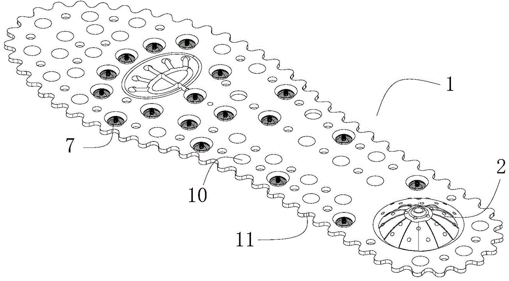
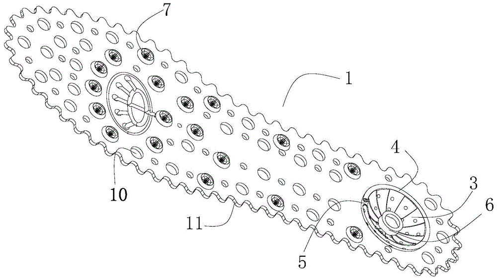
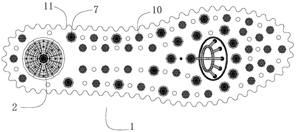
[0034] refer to Figure 1 to Figure 4 , a breathable insole, comprising a pad body 1 with an upper surface and a lower surface, wherein the upper surface is in contact with the sole of the foot, the lower surface is in contact with the sole of the shoe, and at a position corresponding to the heel, the pad body 1 is raised from the lower surface to the upper surface Form the first bulge 2 with elasticity, the lower surface of the first bulge 2 forms a first cavity with the sole, and the lower surface of the cushion body 1 is protruded at the edge of the first bulge 2 for contacting with the sole. The sealing ring 4 is provided with an air outlet 5 on the sealing ring 4 . When the user steps on the pad body 1, the first protruding portion 2 is depressed downwards, and the sealing ring 4, the first protruding portion 2 an...


PUM


Abstract

The invention discloses a breathable insole which comprises an insole body with an upper surface and a lower surface. The upper surface makes contact with the sole of a foot, the lower surface makes contact with a shoe sole, the insole body protrudes from the lower surface to the upper surface at the position corresponding to the heel to form an elastic first protruding portion, the lower surface of the first protruding portion and the shoe sole form a first cavity, the lower surface of the insole body is provided with a sealing ring in contact with the shoe sole in a protruding mode at the edge of the first protruding portion, and the sealing ring is provided with an air outlet. The breathable insole has the advantages that the first protruding portion is good in resilience buffering performance and air replenishment is facilitated; due to the arrangement of the sealing ring and the air outlet, the insole is convenient to detach for washing and breathable; due to the arrangement of a positioning column and an annular magnet, acupoint massage and magnet therapy can be carried out on the foot through the insole conveniently; due to the design of the edge of the insole body of the protruding portion, a small part of the insole can be trimmed conveniently when used so as to be matched with a shoe.

Description

technical field [0001] The invention relates to the field of daily necessities, in particular to a breathable insole. Background technique [0002] Shoes are an essential item in people's daily life. No matter men, women or children, they will use insoles when wearing shoes. Insoles not only have the function of adjusting the size of shoes, but also have the functions of absorbing sweat, degerming and deodorizing. [0003] At present, most of the breathable insoles must cooperate with the sole or be integrated with the sole to produce their breathable function. They only have the hygienic function of isolating the feet and the sole, and their breathability is not good. Existing advanced companies provide a ventilation device that movably assembles the inlet valve and the outlet valve on one side of the airbag, and places them in the groove of the front half of the sole, which is produced by bending the airbag when the user walks. Compression to renew the air, and can be dis...

Claims


Application Information

Patent Timeline
Patent Type & Authority Patents(China)
IPC IPC(8): A43B17/08A61H39/04A61N2/08
Inventor 邹为国
Owner 黄市承
Why Eureka
Try Eureka