Multifunctional mechanical arm for helping physically-challenged people

A manipulator and multi-functional technology, applied in the field of manipulators, can solve the problems of high price, single function, and difficulty, and achieve the effects of wide application range, improved clamping reliability, and reduced manufacturing costs

Inactive Publication Date: 2014-07-23
NORTHEASTERN UNIV
View PDF5 Cites 10 Cited by
  • Summary
  • Abstract
  • Description
  • Claims
  • Application Information

AI Technical Summary

Problems solved by technology

[0002] At present, in the face of many elderly people with limited mobility and people with upper limb disabilities, the manipulator that can help them grasp objects and eat daily meals is an important tool to regain their confidence in "self-reliance". It is still far from perfect. The existing handicap manipulator is not only expensive, but also has a single function. Although it can complete a certain gripping action, the scope of application of the gripping object is small. The object restriction is very large. It is very difficult for a claw that can grip a rectangular object to grip a cylindrical object well, and vice versa.
Moreover, most of the existing grippers do not have an overload protection function, and the gripping force of the grippers is all controlled by sensors, resulting in extremely high cost of the grippers and low gripping reliability.

Method used


Image

  • Multifunctional mechanical arm for helping physically-challenged people
  • Multifunctional mechanical arm for helping physically-challenged people
  • Multifunctional mechanical arm for helping physically-challenged people

Examples


Embodiment Construction

[0017] The present invention will be further described in detail below in conjunction with the accompanying drawings and specific embodiments.

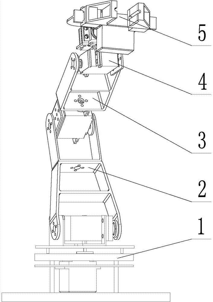
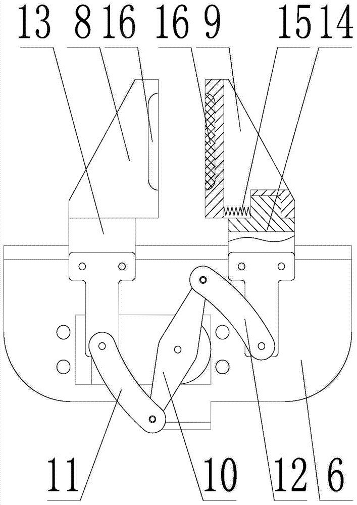
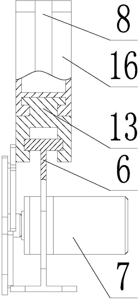
[0018] like figure 1 , 2 As shown in , 3, a kind of multifunctional disabled manipulator comprises support plate 1, big arm 2, forearm 3, wrist 4 and hand claw 5, and described big arm 2 one end is connected with support plate 1, and big arm 2 other end is connected with support plate 1. One end of the forearm 3 is connected, the other end of the forearm 3 is connected with the wrist 4, and the wrist 4 is connected with the gripper 5; the gripper 5 includes a substrate 6, a steering gear 7, a first clamping finger 8 and a second clamping finger 9 , a first slideway is provided on one side of the base plate 6, a first slider 13 is connected to the lower part of the first clamping finger 8, and a second slider 14 is connected to the lower part of the second clamping finger 9, The first clamping finger 8 slides with the substrate 6 thr...


PUM


Abstract

The invention belongs to the technical field of mechanical arms, and relates to a multifunctional mechanical arm for helping physically-challenged people. The mechanical arm comprises a base plate, a steering machine and clamping fingers. A sliding way is arranged on the base plate, the lower portions of the clamping fingers are connected with sliding blocks, the clamping fingers are matched with the base plate through the sliding blocks and the sliding way in a sliding mode, the steering machine is installed on the base plate, and the steering machine and the sliding blocks are connected through a crank link mechanism. The crank link mechanism comprises a crank and a connecting rod, the center of a rod body of the crank is connected with a power output shaft of the steering machine, one end of the crank and one end of the connecting rod are hinged, and the other end of the connecting rod is hinged to the sliding blocks. The sliding blocks are provided with sliding ways, the lower portions of the clamping fingers are provided with sliding grooves, and the clamping fingers are connected with the sliding blocks through the sliding grooves and the sliding ways. Springs are arranged between the sliding blocks and the clamping fingers, and the clamping planes of the clamping fingers are provided with elastic rubber pads. The mechanical arm is provided with a tool connecting handle, the tool connecting handle is matched with the mechanical arm, and the end of the tool connecting handle is connected with a tool. The clamping planes of the clamping fingers are provided with grooves, and the grooves correspond to the tool connecting handle.

Description

technical field [0001] The invention belongs to the technical field of manipulators, in particular to a multifunctional manipulator for assisting the disabled. Background technique [0002] At present, in the face of many elderly people with limited mobility and people with upper limb disabilities, the manipulator that can help them grasp objects and eat daily meals is an important tool to regain their confidence in "self-reliance". It is still far from perfect. The existing handicap manipulator is not only expensive, but also has a single function. Although it can complete a certain gripping action, the scope of application of the gripping object is small. The object restriction is very large, and it is very difficult for a claw that can grip rectangular objects to grip cylindrical objects well, and vice versa. Moreover, most of the existing grippers are not provided with an overload protection function, and the gripping force of the grippers is all controlled by sensors, ...

Claims


Application Information

Patent Timeline
Patent Type & Authority Applications(China)
IPC IPC(8): A61F4/00A61G5/10
Inventor 朱立达曾灿灿罗桂斌
Owner NORTHEASTERN UNIV
Why Eureka
Try Eureka