
A brake shoe clamping mechanism applied to a brake shoe riveting press

A technology of clamping mechanism and brake shoe, which is applied in the direction of brake parts, gear transmission mechanism, clamping, etc., to achieve the effect of satisfying the clamping work

Active Publication Date: 2018-06-01
安徽航大智能科技有限公司
View PDF10 Cites 0 Cited by
  • Summary
  • Abstract
  • Description
  • Claims
  • Application Information

AI Technical Summary

Problems solved by technology

[0003] The purpose of the present invention is to provide a brake shoe clamp for clamping brake shoes of different types or specifications. When removing brake shoes or riveting brake shoes of different sizes, it is necessary to replace the brake shoe fixture of the riveting press

Method used


Image

  • A brake shoe clamping mechanism applied to a brake shoe riveting press
  • A brake shoe clamping mechanism applied to a brake shoe riveting press
  • A brake shoe clamping mechanism applied to a brake shoe riveting press

Examples


Embodiment Construction

[0016] The technical solutions of the present invention will be clearly and completely described below in conjunction with the embodiments. Apparently, the described embodiments are only some of the embodiments of the present invention, not all of them. Based on the embodiments of the present invention, all other embodiments obtained by persons of ordinary skill in the art without creative efforts fall within the protection scope of the present invention.

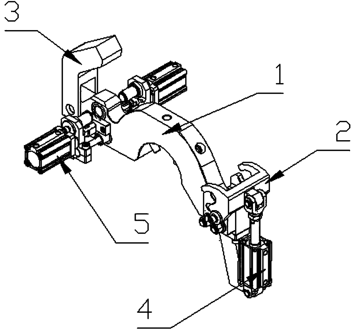
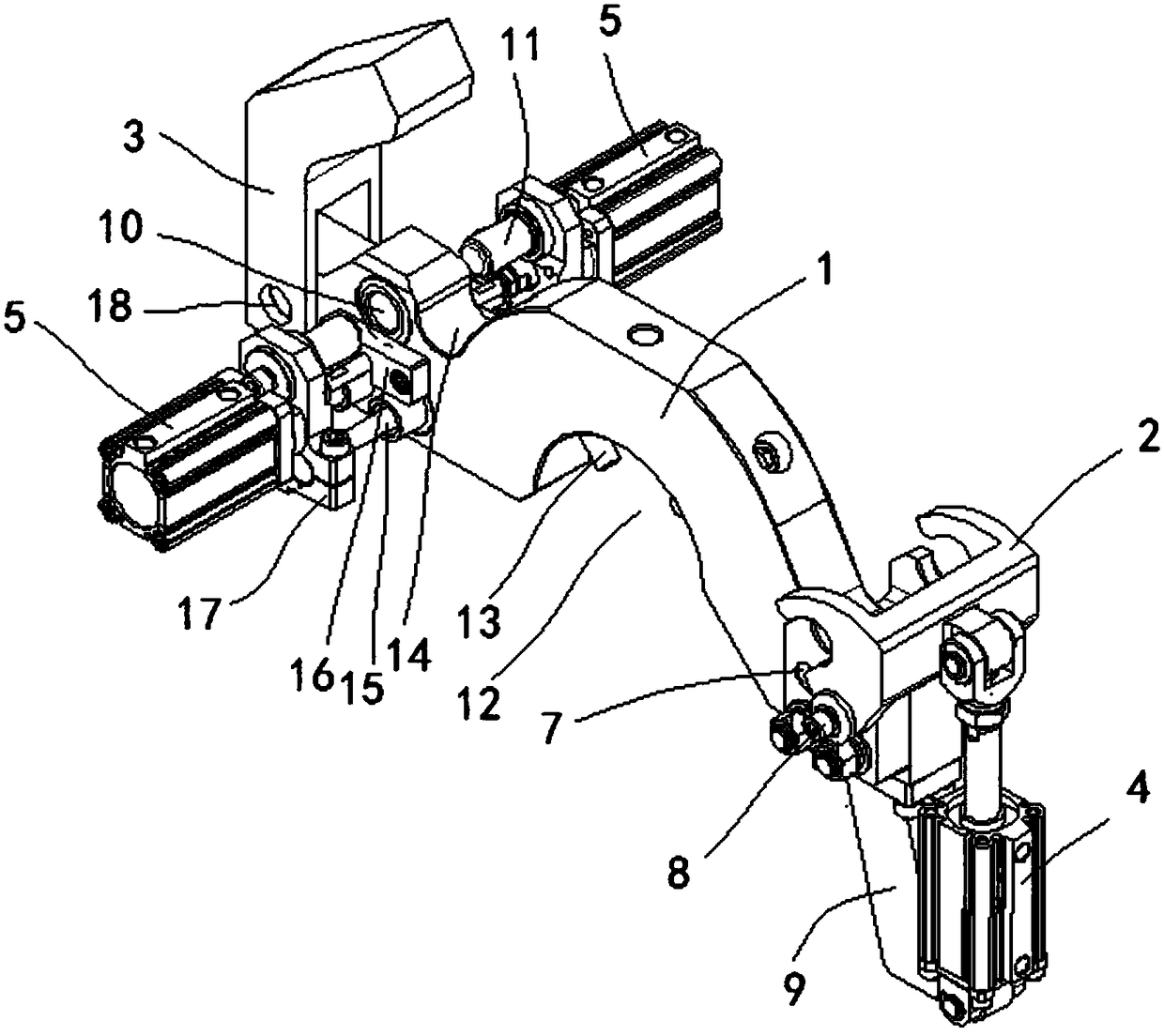
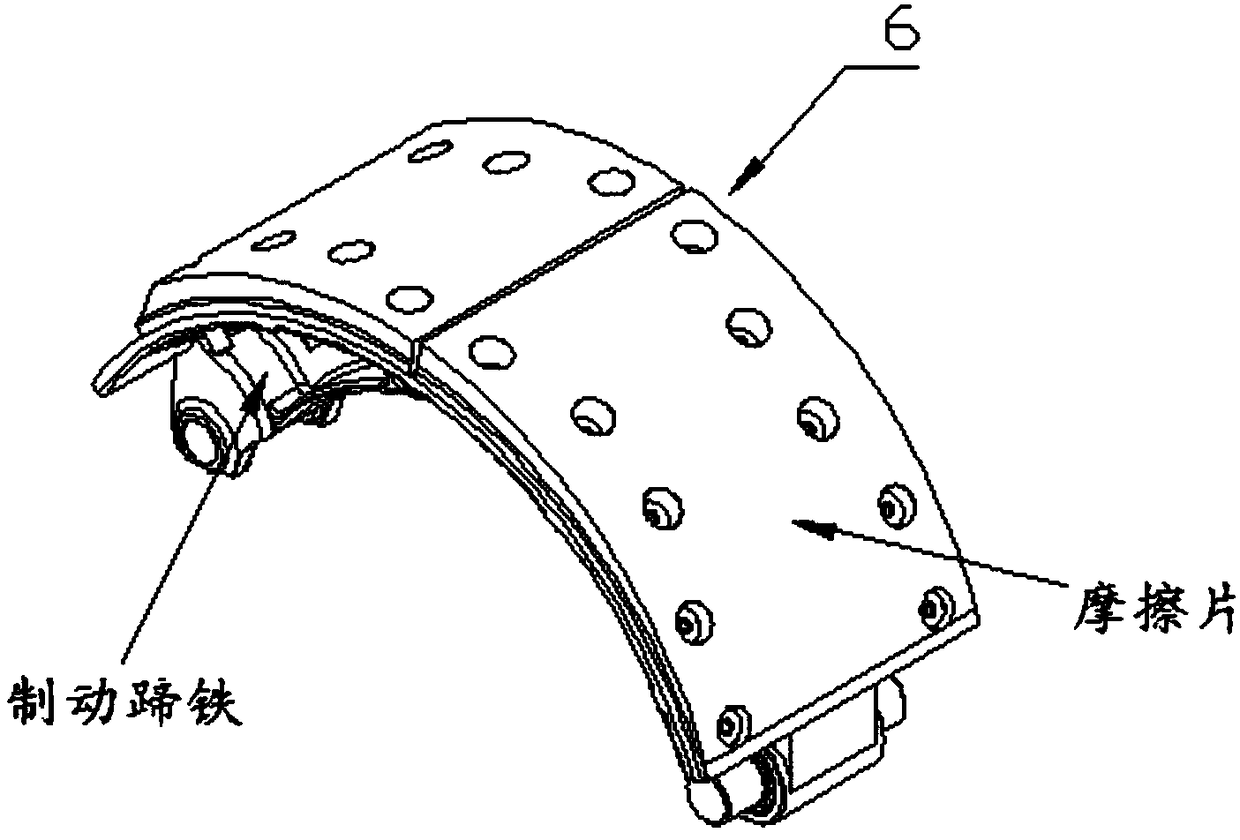
[0017] A brake shoe clamping mechanism applied to a brake shoe riveting press. According to different models or sizes of brake shoes, most of the brake shoes are equipped with arc surface friction plates, but only the size of the arc surface is different or Different widths are designed for this feature, see figure 1 , image 3 , including adjustable brake shoe mounting base 1, front jaw 2, rear jaw 3, front jaw adjustment cylinder 4, and clamping cylinder 5, which can be used for clamping and position;

[0018] see fi...


PUM


Abstract

The invention discloses a brake shoe clamping mechanism applied to a brake shoe riveting press. The brake shoe clamping mechanism comprises a brake shoe adjustable mounting seat, a front claw, a rear claw, a front claw adjusting cylinder and clamping cylinders. The brake shoe adjustable mounting seat is connected with a rotating shaft of the riveting press in a fastening manner. The rear claw is mounted in a rear-end fixed shaft hole in the brake shoe adjustable mounting seat through a shaft. A groove is formed in the rear end of the brake shoe adjustable mounting seat. The two top-end clamping cylinders are mounted on two sides of the rear end of the brake shoe adjustable mounting seat. An arc-shaped long hole is formed in the front end of the brake shoe adjustable mounting seat. The front claw is mounted in the arc-shaped long hole through a shaft. The front claw is connected with a cylinder rod of the front claw adjusting cylinder. Through the design that the rear claw is a fixed mechanical claw, and the front claw is a movable adjustable claw, the clamping mechanism for a brake shoe has the characteristics of high stability and high flexibility, and clamping of the brake shoes of different radians can be realized.

Description

technical field [0001] The invention belongs to the technical field of brake shoe riveting and clamps, and in particular relates to a brake shoe claw clamp applied to a brake shoe riveting press. Background technique [0002] Brake shoe riveting is a necessary link in the production process of brake shoes today. Since the brake shoes usually have an arc shape or irregular shape, correctly grasping and fixing the brake shoe during the riveting process of the brake shoe becomes an important factor affecting the riveting result of the brake shoe. At present, most of the brake shoe riveting machines on the market are riveted by the operator using hand or auxiliary machinery to clamp the brake shoe to the riveting machine. Human factors cause the riveting effect to be unsatisfactory, and most of them are equipped with proprietary fixtures. The current riveting press can only clamp one type of brake shoe. Contents of the invention [0003] The purpose of the present invention ...

Claims


Application Information

Patent Timeline
Patent Type & Authority Patents(China)
IPC IPC(8): B23Q3/08F16D65/04
CPCB21J15/14B21J15/42F16D65/04F16D2250/0084
Inventor 刘军张景亮韩鹏朱淳逸郑大维
Owner 安徽航大智能科技有限公司
Learn More