Bridge equipment

A technology for equipment and bridges, applied in the field of bridge equipment, can solve problems such as poor protection performance, damage to power supply equipment, and unstable insertion force, so as to prevent unstable insertion, improve work efficiency, and reduce equipment investment.

Active Publication Date: 2017-06-09
江苏源清环保科技有限公司
View PDF5 Cites 70 Cited by
  • Summary
  • Abstract
  • Description
  • Claims
  • Application Information

AI Technical Summary

Problems solved by technology

[0002] Electrified maintenance equipment is often used in the daily maintenance of some bridges. The electrified equipment needs to be plugged in for power supply before it can be used. However, in the bridge infrastructure construction, there are fewer power supply seats and the relative settings are too simple. The electrified maintenance equipment is connected to its power supply through the plug-in method. Although the plug-in method is simple, its tightness is not high, and it will shake with the electrified maintenance equipment when it moves, causing the plug-in to loosen and fail to work normally. Power supply connection, at the same time, the stability of manual plugging is poor, and arcing is easy to occur during the plugging process. The generation of arcing is likely to cause electric shock to users, which has certain potential dangers to users, which will cause safety accidents and cause casualties. The plugging force is unstable, which can easily lead to damage to the power supply equipment. At the same time, it is time-consuming and labor-intensive, which has great disadvantages. In addition, the existing bridge power supply equipment does not have a prompt function when the power supply is connected, making it difficult for maintenance personnel to know the best plug-in. In the state of power supply, the protection performance is too poor, which brings great inconvenience to users

Method used


Image

  • Bridge equipment
  • Bridge equipment
  • Bridge equipment

Examples


Embodiment Construction

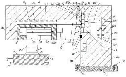
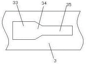
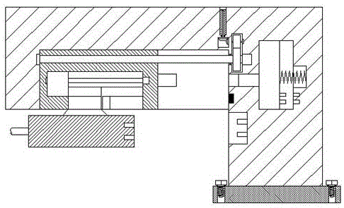
[0027] Such as Figure 1-Figure 8 As shown, a bridge device of the present invention includes a base body 1, a frame body 2 fixedly arranged on the upper left side of the base body 1, and an electrical connector 4, and an insertion slot is provided in the base body 1 below the frame body 2 11. The first electrical contact pin 111 is provided in the insertion groove 11, and the first slide slot 21 is provided in the bottom end surface of the right side of the frame body 2, and the locking part 3 is provided in the first slide slot 21 , the first chute 21 is provided with a first stud 211 threadedly connected with the locking part 3 and extending to the left and right sides, and the base 1 on the right side of the frame 2 is provided with a second A sliding chamber 12, a communication groove 13 is provided between the first sliding chamber 12 and the first sliding groove 21, and a first hollow chamber 16 is provided in the substrate 1 above the communication groove 13, The fram...


PUM


Abstract

The invention discloses bridge equipment. The bridge equipment comprises a base body, a frame body and an electric connector, wherein the frame body is fixedly arranged on the left upper side of the base body; an inserting groove is formed in the base body under the frame body,; a first electric connecting pin is arranged in the inserting groove; a first slide groove is formed in the end surface of the bottom of the right side of the frame body; a locking part is arranged in the first slide groove; a first stud, which is connected with the locking part in a screw-thread fit manner and extends to the left side and the right side, is arranged in the first slide groove; a first slide cavity is formed in the base body on the right side of the frame body; a communication groove is formed between the first slide cavity and the first slide groove; a first hollow cavity is formed in the base body above the communication groove; a second groove bottom is arranged in the frame body above the right side of the first slide groove; a second slide groove, which runs through the top wall of the frame body, is formed in a position, above the second groove part, in the frame body; a pushing and pressing rod, which is arranged oppositely to the left side end of the communication groove, is arranged on the end surface of the right side of the locking part; a slide block is connected in the first slide cavity in a loose fit manner. The bridge equipment disclosed by the invention has the advantages of simple structure, convenient inserting, automatic locking and inserting, and has an intelligent prompting function.

Description

technical field [0001] The invention relates to the technical field of bridge facilities, in particular to bridge equipment. Background technique [0002] Electrified maintenance equipment is often used in the daily maintenance of some bridges. The electrified equipment needs to be plugged in for power supply before it can be used. However, in the bridge infrastructure construction, there are fewer power supply seats and the relative settings are too simple. The electrified maintenance equipment is connected to its power supply through the plug-in method. Although the plug-in method is simple, its tightness is not high, and it will shake with the electrified maintenance equipment when it moves, causing the plug-in to loosen and fail to work normally. Power supply connection, at the same time, the stability of manual plugging is poor, and arcing is easy to occur during the plugging process. The generation of arcing is likely to cause electric shock to users, which has certain...

Claims


Application Information

Patent Timeline
Patent Type & Authority Applications(China)
IPC IPC(8): E01D22/00
CPCE01D22/00
Inventor 廖文华
Owner 江苏源清环保科技有限公司
Why Eureka
Try Eureka