Fluorescence microscope, display method using fluorescence microscope system, and computer-readable medium

a microscope and fluorescence technology, applied in the field of fluorescence microscope, display method using fluorescence microscope system, and computer-readable medium, can solve the problems of limited case availability, limited margin of choice, and attenuation of background light, and achieve the effect of reducing cost and reducing damage to specimens

Inactive Publication Date: 2005-12-08
KEYENCE
View PDF11 Cites 73 Cited by
  • Summary
  • Abstract
  • Description
  • Claims
  • Application Information

AI Technical Summary

Benefits of technology

[0011] In order to attain the above object, a fluorescence microscope of the present invention comprises plural types of filter sets 1 including a combination of a predetermined excitation filter 12, a dichroic mirror 14, and an absorption filter 16 as optical members constituting an optical system 10; a filter switch portion 18 for switching the filter sets 1 at a predetermined timing; a switching set portion 20 for setting a timing at which the filter switch portion 18 switches the filter sets 1; an imaging portion 22 for picking up an image of a specimen W as an observation object by using the filter sets 1 that are set on an optical path of the optical system 10 by the filter switch portion 18; a display portion 24 having a plurality of image display areas G on which the image picked up by the imaging portion 22 is displayed respectively; and a control portion 26 for generating a superposed image that is formed by superposing the image picked up by the imaging portion 22. This fluorescence microscope is constructed such that the image picked up by using any filter sets (1) can be displayed in at least an area of the image display areas (G), and the superposed image that is formed by superposing the image picked up by using any filter sets (1) respectively can be displayed in another area of the image display areas (G). Accordingly, the images such as the monochromatic fluorescent image picked up by using each filter set, etc. and the superposed image formed by superposing these images in a multiple mode can be displayed automatically, and thus the observation can be easily made by comparing these images.
[0032] According to the fluorescence microscope, the display method using the fluorescence microscope system, the fluorescence microscope image display program, and the computer-readable recording medium and the storing device, the superposed image in which respective fluorescent colors are superposed can be displayed / updated in almost real time in the multicolor fluorescent observation. This is because the switching of the filter set can be automated and the superposed image of respective images can be formed in seriatim at the same time, and also such superposed image can be displayed on the display portion. Since this imaging process can be repeated automatically, the drawing of respective images can be continued while being updated in almost real time. As a result, the quasi-real time observation as the multicolor fluorescent observation that only the laser microscope can carry out in the related art can be realized by the fluorescence microscope, and thus the excellent multicolor fluorescent observation that inflicts little damage on the specimen can be carried out at a lower cost.

Problems solved by technology

This attenuates the background light as an obstacle to observation.
However, in the method of using the dual / triple bandpass filter, since the available combination of the fluorescent pigments is restricted due to the characteristic of the filter set, a margin of choice is restricted.
That is, there is the problem that the available cases are limited.
Also, there is the problem that, since a plurality of colors are passed, the color separation characteristic is worsened and thus the crosstalk is generated.
In addition, there is the problem that the monochromatic image cannot be observed.
Therefore, it is impossible to observe in real time what superposition is given by respective colors.
Also, there is the problem that the filter set must be switched manually one by one to pick up the image every filter set and thus the operation becomes complicated.
However, there exists the problem that, since the laser light is used as the excitation light source in the laser microscope, the excitation light is very strong and thus the specimen is considerably damaged when the excitation light is irradiated onto the specimen, so that the living cells are damaged or the fading of the fluorescent color is caused.
In particular, the extent of damage gets worse every time when the scanning is repeated.
Thus, there also exists the problem that the system becomes expensive.
In particular, the laser must be exchanged periodically and thus a heavy burden of the running cost or the cost of maintenance is imposed.

Method used


Image

  • Fluorescence microscope, display method using fluorescence microscope system, and computer-readable medium
  • Fluorescence microscope, display method using fluorescence microscope system, and computer-readable medium
  • Fluorescence microscope, display method using fluorescence microscope system, and computer-readable medium

Examples


Embodiment Construction

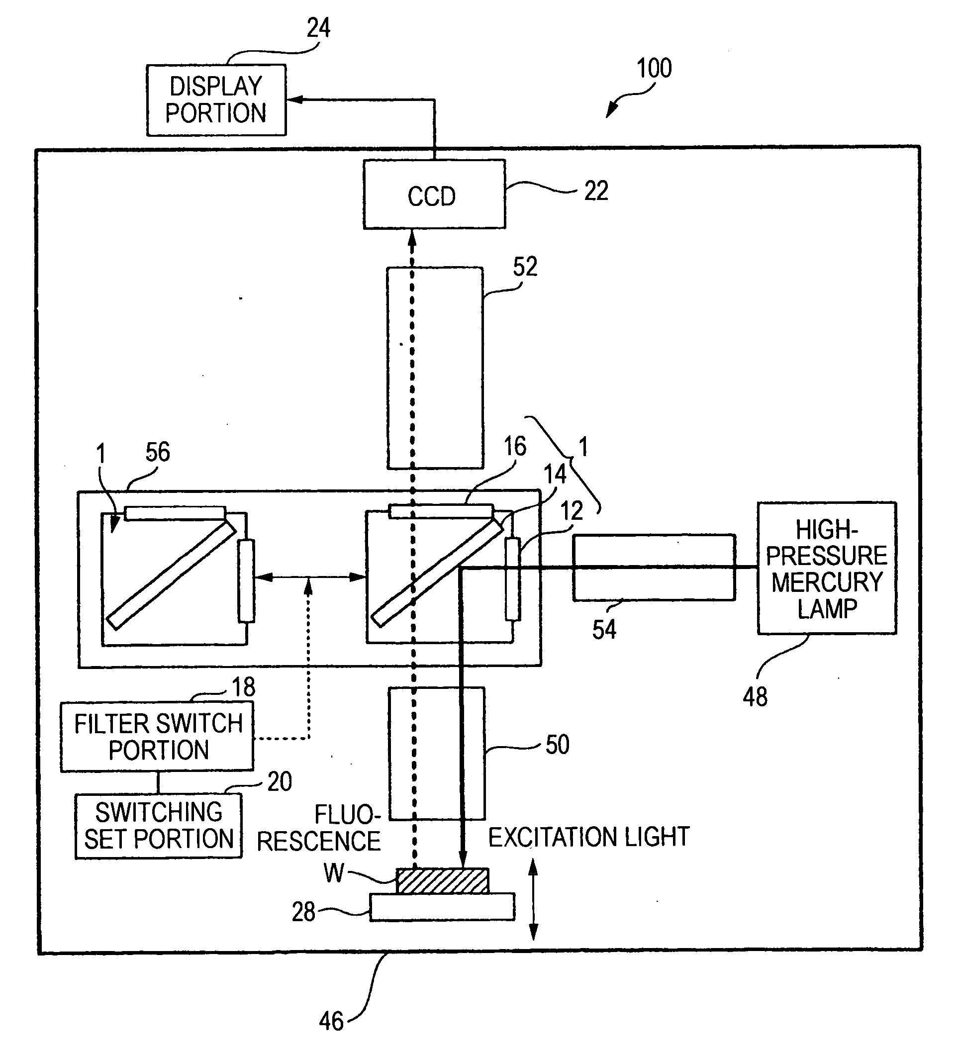
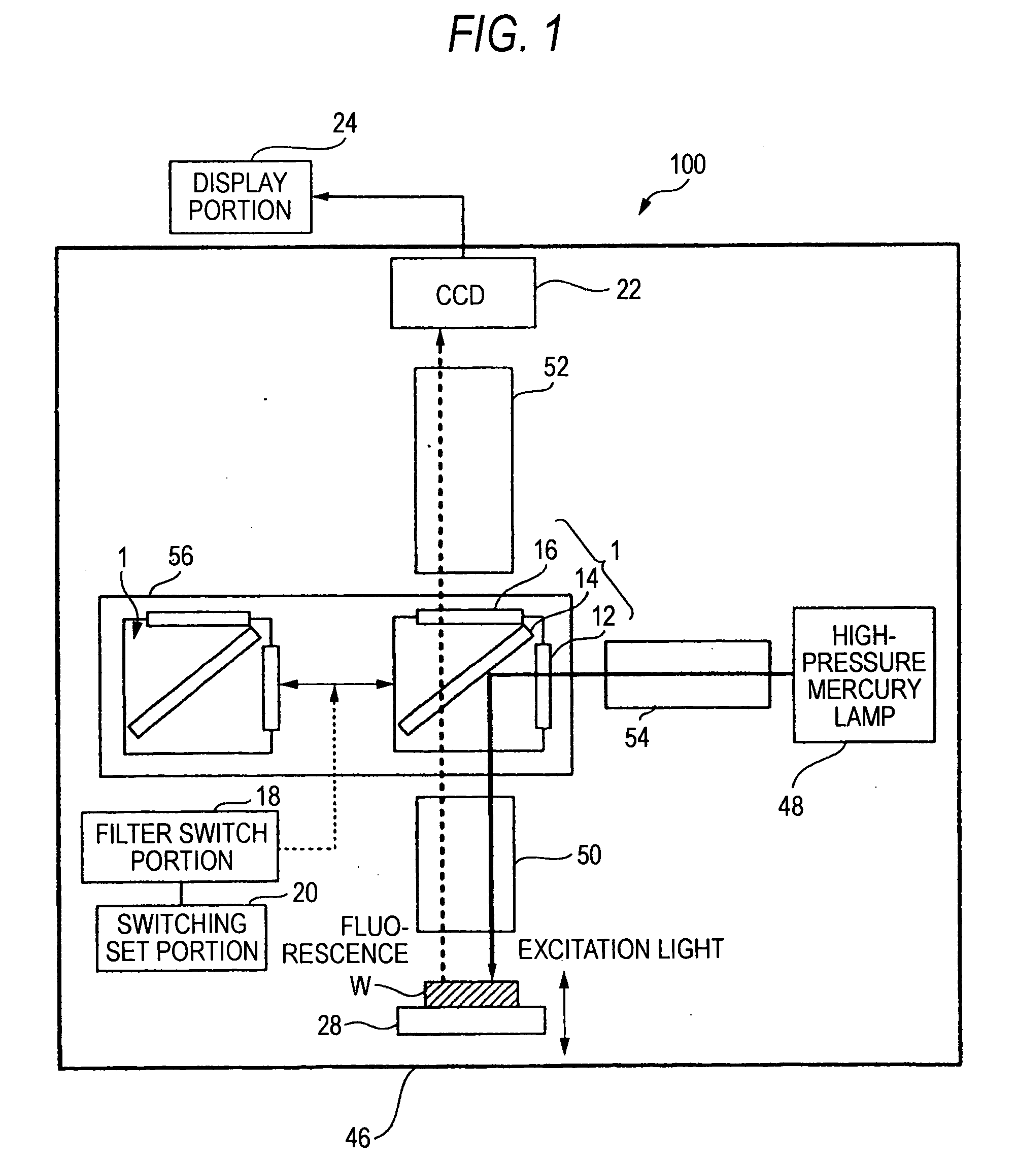
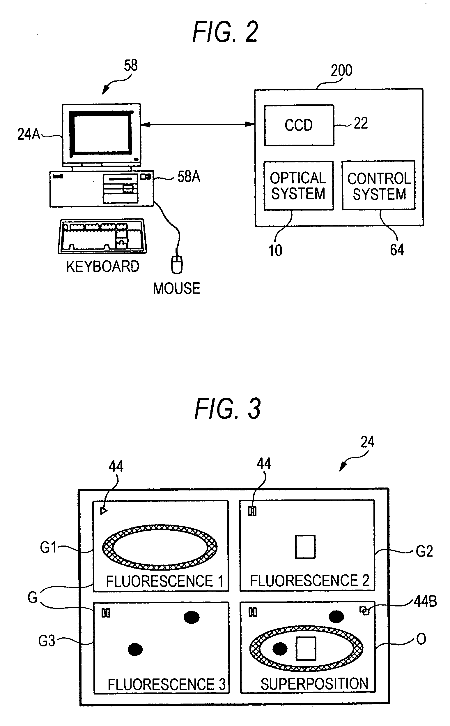
[0043] Embodiments of the present invention will be explained with reference to the drawings hereinafter. In this case, the embodiments described in the following should be interpreted as mere illustrations of the fluorescence microscope, the display method using the fluorescence microscope system, the fluorescence microscope image display program, and the computer-readable recording medium and the storing device, which embody the technical ideas of the present invention. The present invention should not be interpreted to restrict the fluorescence microscope, the display method using the fluorescence microscope system, the fluorescence microscope image display program, and the computer-readable recording medium and the storing device to those described in the following. Also, in order to facilitate the understanding of claims, reference numerals corresponding to the members shown in the embodiments are affixed to the members described in the “column of Claims” and the “column of Sum...


PUM

PropertyMeasurementUnit
exposure timeaaaaaaaaaa
fluorescence microscopeaaaaaaaaaa
distanceaaaaaaaaaa

Abstract

A fluorescence microscope comprises plural types of filter sets including a combination of a excitation filter, a dichroic mirror, and an absorption filter, a filter switch portion for switching the filter sets at a predetermined timing, an imaging portion for picking up an image of a specimen as an observation object by using the filter sets, a display portion having a plurality of image display areas on which the image picked up by the imaging portion are displayed respectively, and a control portion for generating a superposed image on which the images are superposed. In this fluorescence microscope, the imaging portion picks up the image via every filter set in synchronism with a timing which is set by the switching set portion and at which the filter switch portion switches the filter sets, and then the picked-up image is automatically updated and displayed in the image display areas.

Description

[0001] The present application claims foreign priority based on Japanese Patent Application No. 2004-152544, filed May 21, 2004, the contents of which is incorporated herein by reference. BACKGROUND OF THE INVENTION [0002] 1. Technical Field [0003] The present invention relates to a fluorescence microscope having a function of displaying an image of a specimen, a display method using a fluorescence microscope system, and a computer-readable medium. [0004] 2. Related Art [0005] Conventionally, in order to observe the microstructure of a cell and localization of a molecule, a fluorescence microscope or a laser microscope has been used. On the fluorescence microscope, a fluorescent molecule that is specifically bonded with a particular target molecule in the specimen is attached to the target molecule in order to observe distribution and behavior of the target molecule. The fluorescent molecule is also called a fluorescent probe and includes, for example, a fluorescent molecule covalen...

Claims


Application Information

Patent Timeline
Patent Type & Authority Applications(United States)
IPC IPC(8): G02B21/16G02B21/24G02B21/26G01N21/64G02B21/00G02B21/36G02B7/00
CPCG02B21/0088G02B21/16G02B21/26G02B21/367G02B26/007
Inventor MIKI, MASAYUKI
Owner KEYENCE
Why Eureka
Try Eureka