
Bearing support frame

A bearing support frame and bearing technology, applied in the field of support frames, can solve the problems of unstable shaft rotation, easy shaking, inconvenient installation, etc., and achieve the effects of simple structure, convenient fixing of bearings, and convenient installation and disassembly.

Inactive Publication Date: 2014-07-23
熊世武
View PDF6 Cites 2 Cited by
  • Summary
  • Abstract
  • Description
  • Claims
  • Application Information

AI Technical Summary

Benefits of technology

This new technology makes it easier for people who want to fix their bearings without having any extra connections like bolts or other fasteners that might be needed. It's also easy-to use with existing equipment.

Problems solved by technology

This patented technical problem addressed by this patents relates to improving lubrication between movable members such as rollers and bushes in machinery systems without making them more complicated than traditional methods like grease injection.

Method used


Image

  • Bearing support frame

Examples


Embodiment Construction

[0011] In order to make the technical means, creative features, goals and effects achieved by the present invention easy to understand, the present invention will be further described below in conjunction with specific illustrations.

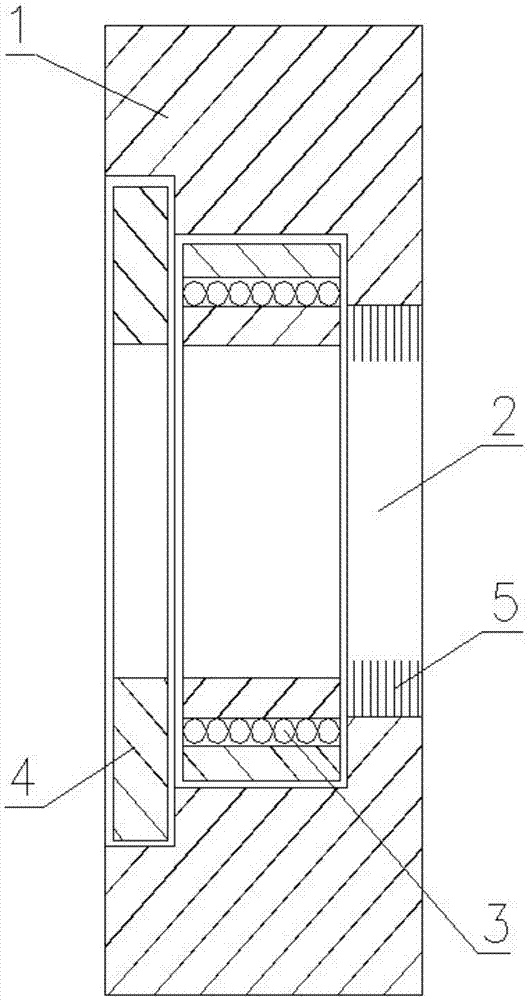
[0012] Such as figure 1 The shown bearing support frame mainly includes a support plate 1, a stepped circular hole 2 is provided on the support plate 1, a bearing 3 is placed in the stepped circular hole 2, and a circular plate 4 is covered on the bearing 3, and the circular plate 4 and the The support plate 1 is connected by screws, wherein the stepped round hole 2 is a three-step stepped round hole, followed by a large, medium and small single round hole. The bearing 3 is placed in the middle round hole, and the ring plate 4 is placed in the largest round hole. The inner surface of the smallest circular hole is provided with a hairbrush 5 .

[0013] The basic principles, main features and advantages of the present invention have been shown an...


PUM


Abstract

The invention discloses a bearing support frame, and relates to a support frame. The support frame mainly comprises a support plate, wherein the support plate is provided with a step round hole; and a bearing is arranged in the step round hole, an annulus plate is covered with the bearing, and the annulus plate is connected with the support plate through a bolt. The bearing support frame provided by the invention has the advantages that the structure is simple, the design is reasonable, connecting pieces such as the bolt do not need to be added on the bearing, the installation and disassembly are convenient, the bearing is conveniently fixed, and the bearing support frame is simple and useful.

Description


Claims


Application Information

Patent Timeline
Owner 熊世武
Learn More