Rotating disc driving type rotary spraying device for ocean drilling platform pile shoe assistant lifting

An ocean drilling platform, driven technology, applied in the direction of sheet pile wall, building, infrastructure engineering, etc., can solve the problems that can not achieve the effect of rapid spraying and boosting, the area of ​​spraying is small, and the adsorption of sediment on the seabed cannot be quickly removed. , to achieve the effect of releasing the package adsorption, improving the effect of spraying and increasing the area of ​​spraying

Inactive Publication Date: 2014-07-30
齐宝兰
View PDF7 Cites 3 Cited by
  • Summary
  • Abstract
  • Description
  • Claims
  • Application Information

AI Technical Summary

Problems solved by technology

[0002] The direction of the water column ejected by the jetting head of the jetting device in the prior art is fixed, so the action range of the jetting sediment is distributed in a point line, and the jetting area is small, and it is impossible to quickly remove the adsorption of the seabed sediment to the outer surface of the spud can. Can not achieve the best rapid spray boost effect

Method used


Image

  • Rotating disc driving type rotary spraying device for ocean drilling platform pile shoe assistant lifting
  • Rotating disc driving type rotary spraying device for ocean drilling platform pile shoe assistant lifting
  • Rotating disc driving type rotary spraying device for ocean drilling platform pile shoe assistant lifting

Examples


Embodiment

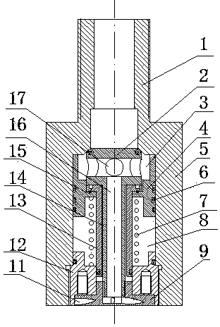
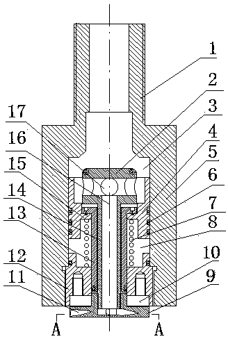
[0016] The spray flushing device working process of the present invention is as follows:

[0017] High-pressure water enters from the interface pipe, pushes the rotating valve core to move down, and the rotating valve core moves down in conjunction with the annular piston, valve core, valve stem and rotary jet drive plate to move down and protrude out of the concave hole at the bottom of the end cover. During the downward movement, high-pressure water enters the valve cavity, then enters the water inlet in the middle of the valve core, and enters the vortex nozzle hole in the middle of the rotary spray drive plate through the outlet pipe in the center of the valve stem, and is sprayed outwards. Drive the rotary jet drive plate to rotate, and drive the rotary valve core to rotate as a whole to implement the rotary jet flushing and cleaning operation. When the high-pressure water of the interface pipe is closed, the annular piston moves up and resets under the action of the retu...


PUM


Abstract

The invention provides a rotating disc driving type rotary spraying device for ocean drilling platform pile shoe assistant lifting. The structure comprises a shell body, an annular piston, a rotating valve core, a valve rod sleeve, an end cover and a reset spring, wherein a valve cavity is formed in the middle of the shell body, a connection pipe is arranged at the upper end of the shell body, the pipe cavity of the connection pipe is communicated with the valve cavity, the end cover is in thread connection onto the lower end of the valve cavity, a through hole is vertically formed in the center of the end cover, the annular piston is arranged in the middle of the valve cavity, a concave ring is arranged in the middle hole of the annular piston, the upper part of the concave ring and the upper end of the valve rod sleeve are connected, the lower end of the valve rod sleeve is inserted into the central through hole in the end cover, the rotating valve core is formed by a valve core, a valve rod and a rotary spraying driving disc, the valve core and the rotary spraying driving disc are arranged at the upper end and the lower end of the valve rod, a water inlet hole is horizontally formed in the middle of the valve core, a water outlet pipeline is arranged in the center of the valve rod, a vortex spraying hole is horizontally formed in the rotary spraying driving disc, and the vortex spraying hole is communicated with a water inlet through the water outlet pipeline. The valve core rotates automatically during spraying and washing, the spraying and washing area is increased, the spraying and washing effect is improved, the device can rapidly eliminate the coating and adsorbing of submarine sludge to a pile shoe, the lifting of the pile shoe is accelerated, and the work area transferring cycle of a petrol platform is shortened.

Description

technical field [0001] The invention relates to the technical field of offshore oil drilling platforms, in particular to a turntable-driven swirling device for lifting boots of offshore drilling platforms. Background technique [0002] The direction of the water column sprayed out by the jetting head of the jetting device in the prior art is fixed, so the action range of the jetting sediment is distributed in a point line, and the jetting area is small, and it is impossible to quickly remove the adsorption of the seabed sediment on the outer surface of the spud can. Can not reach the best rapid spraying and boosting effect. Contents of the invention [0003] The technical task of the present invention is to solve the deficiencies of the prior art, and provide a turntable-driven swirling device for spud shoe lifting of an offshore drilling platform. [0004] The technical scheme of the present invention is realized in the following manner. The rotary spray flushing device ...

Claims


Application Information

Patent Timeline
Patent Type & Authority Applications(China)
IPC IPC(8): E02D13/08
Inventor 齐宝兰
Owner 齐宝兰
Why Eureka
Try Eureka