Lower vortex hole driving rotary spraying device for ocean drilling platform pile shoe assistant lifting

A technology for offshore drilling platforms and spud boots, which is applied to sheet pile walls, buildings, and foundation structure engineering, etc. It can solve problems such as the inability to achieve the effect of rapid spraying and lifting, the small area of ​​spraying, and the inability to quickly remove the adsorption of seabed sediment. , to achieve the effect of shortening the transfer cycle of the work area, improving the effect of spraying and accelerating the lifting

Inactive Publication Date: 2014-07-30
齐宝兰
View PDF5 Cites 2 Cited by
  • Summary
  • Abstract
  • Description
  • Claims
  • Application Information

AI Technical Summary

Problems solved by technology

[0002] The direction of the water column ejected by the jetting head of the jetting device in the prior art is fixed, so the action range of the jetting sediment is distributed in a point line, and the jetting area is small, and it is impossible to quickly remove the adsorption of the seabed sediment to the outer surface of the spud can. Can not achieve the best rapid spray boost effect

Method used


Image

  • Lower vortex hole driving rotary spraying device for ocean drilling platform pile shoe assistant lifting
  • Lower vortex hole driving rotary spraying device for ocean drilling platform pile shoe assistant lifting
  • Lower vortex hole driving rotary spraying device for ocean drilling platform pile shoe assistant lifting

Examples


Embodiment

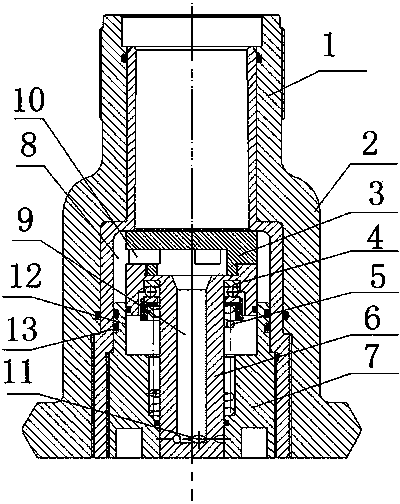
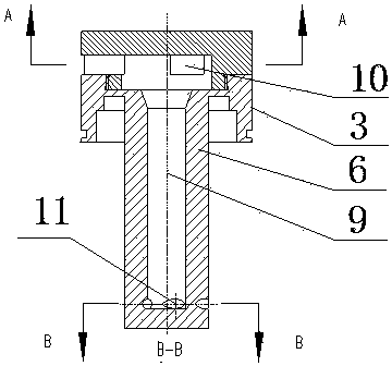
[0017] The working process of the rotary jet punching device of the present invention is as follows:

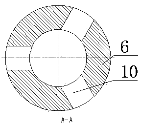
[0018] High-pressure water enters from the interface pipe, pushing the valve core down, the valve core is linked with the valve stem to move down, the lower end of the valve stem extends out of the end cap, the high-pressure water enters the interface pipe, and then enters the valve cavity through the water inlet into the blind hole in the center of the valve stem , And then follow the blind hole to spray out from the rotary injection hole at the lower end of the valve stem. Since the center line of the rotary injection hole is tangent to the circle of the blind hole, the rotary injection hole produces a reaction force on the valve stem during the injection process, causing the valve stem to rotate. The water is sprayed out in a disc shape. When the high-pressure water in the mouthpiece is closed, the valve stem moves up with the valve core, and the rotary spray hole at the lower...


PUM


Abstract

The invention provides a lower vortex hole driving rotary spraying device for ocean drilling platform pile shoe assistant lifting. The device comprises a shell body, a valve core, a valve rod, an end cover and a reset spring, wherein a valve cavity is arranged in the middle of the shell body, a connection pipe is arranged at the upper end of the shell body, the pipe cavity of the connection pipe is communicated with the valve cavity, the end cover is in thread connection onto the lower end of the valve cavity, a through hole is vertically formed in the center of the end cover, a valve structure is formed by connecting the top edge of the valve core and the lower pipe mouth of the connection pipe, the valve rod is arranged at the lower end of the valve core, a blind hole is formed in the center of the valve rod, a water inlet hole is horizontally formed in the middle of the valve core, a rotary spraying hole is formed in the lower end of the valve rod, the rotary spraying hole is communicated with the water inlet hole through the blind hole, the outer circle of the lower end of the valve rod penetrates through the vertical through hole in the center of the end cover, the reset spring sleeves the outer circle of the valve rod, the lower end of the reset spring is connected with the upper end of the end cover, and the upper end of the reset spring is connected with a thrust bearing at the bottom of the valve core. The valve core rotates automatically during spraying and washing, the point-line spraying and washing in the prior art is changed into the rotary surface spraying and washing, the spraying and washing area is increased, and the spraying and washing effect is improved.

Description

technical field [0001] The invention relates to the technical field of offshore oil drilling platforms, in particular to a lower vortex hole driven swirling device for spud shoe lifting of the offshore drilling platform. Background technique [0002] The direction of the water column sprayed out by the jetting head of the jetting device in the prior art is fixed, so the action range of the jetting sediment is distributed in a point line, and the jetting area is small, and it is impossible to quickly remove the adsorption of the seabed sediment on the outer surface of the spud can. Can not reach the best rapid spraying and boosting effect. Contents of the invention [0003] The technical task of the present invention is to solve the deficiencies of the prior art, and provide a lower vortex hole-driven swirling device for spud shoe lifting of an offshore drilling platform. [0004] The technical solution of the present invention is realized in the following manner. The rota...

Claims


Application Information

Patent Timeline
Patent Type & Authority Applications(China)
IPC IPC(8): E02D13/08
Inventor 齐宝兰
Owner 齐宝兰
Why Eureka
Try Eureka