Vehicle-mounted particle concentration detector

A particle concentration and detector technology, applied in the field of detectors, can solve the problems of finding out the concentration change, particle damage to the internal structure, only detecting the particle concentration inside the vehicle, or the particle concentration outside the vehicle, etc., so as to achieve comprehensive detection results and avoid particulate matter. effect of deposition

Active Publication Date: 2014-07-30
张家港谱析传感科技有限公司
View PDF8 Cites 7 Cited by
  • Summary
  • Abstract
  • Description
  • Claims
  • Application Information

AI Technical Summary

Problems solved by technology

However, the current vehicle-mounted particle concentration detector has the following defects: 1. The current concentration detector generally only detects the particle concentration in the same environment, for example, only detects the particle concentration inside the car, or the particle concentration outside the car, and the detection results cannot be compared Obtaining the difference between the environment inside and outside the current car, it is impossible to find out the problem of the concentration change according to the test results; 2. Since the detector sucks the air with particulate matter into the detector for detection, the usage time of the sampling pump of the detector Long, particles damage the internal structure; 3. During the use of the spherical reflector of the laser dust concentration sensor of the current detector, particles are easily stuck to the spherical surface of the reflector, and this phenomenon will affect the light radiation effect of the spherical reflector Therefore, regular disassembly and cleaning are required, and the current spherical reflector is installed on the laser dust concentration sensor, which is located inside the detector. Complicated, cumbersome disassembly, too many disassembly parts will easily affect the assembly accuracy

Method used


Image

  • Vehicle-mounted particle concentration detector
  • Vehicle-mounted particle concentration detector

Examples


Embodiment Construction

[0019] The present invention will be described in further detail below through specific examples.

[0020] Up, down, left and right described in the present invention are based on figure 1 The direction in which the detector is placed is determined. At the same time, the low concentration and high concentration described in the present invention do not need to be defined by specific values, and are obtained by comparing two environments with different concentrations.

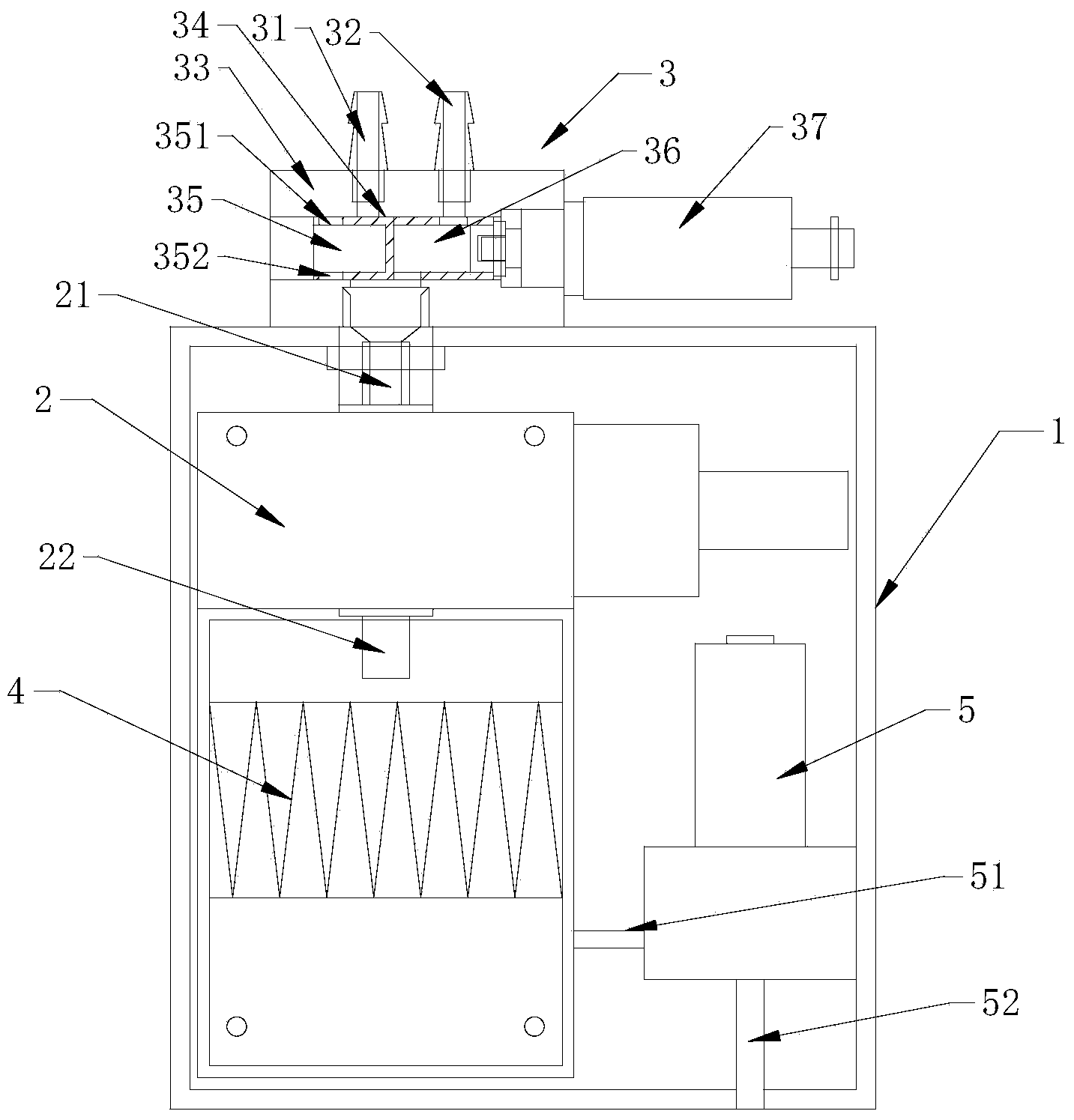
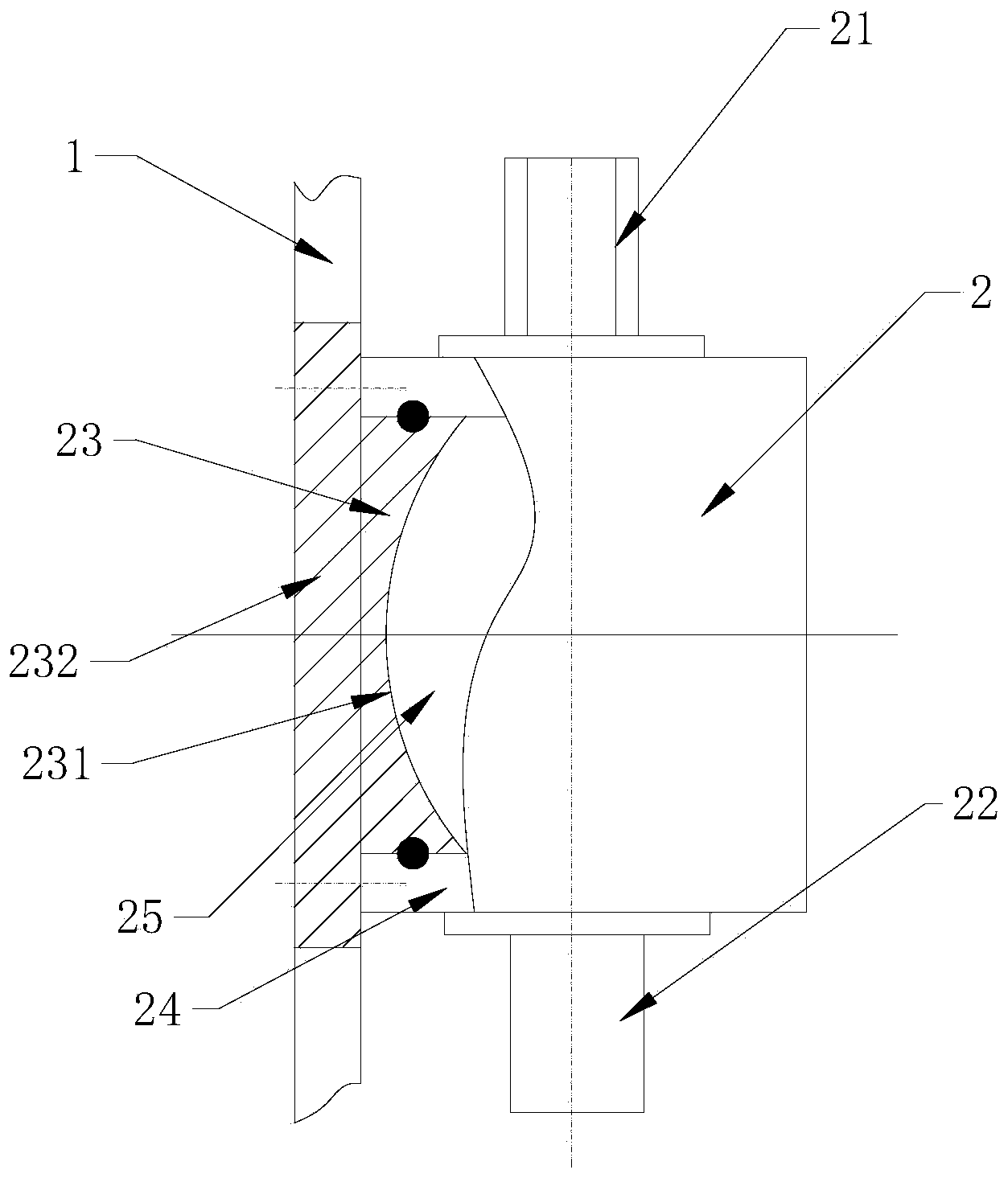
[0021] Such as figure 1 , 2 As shown, a vehicle-mounted particle concentration detector includes a housing, a laser dust concentration sensor, a sampling pump, and a sampling distribution valve.

[0022] The laser dust concentration sensor is fixed in the casing, the laser dust concentration sensor includes a casing, a laser light source, a photoelectric detector and a spherical mirror, the casing is fixed in the casing, and a dust concentration detection chamber is arranged in the casing, The housing is prov...


PUM


Abstract

The invention discloses a vehicle-mounted particle concentration detector which comprises a shell, a laser dust concentration sensor, a sampling pump and a sampling distribution valve, wherein the sampling distribution valve is arranged outside the shell and comprises a valve body and a valve core; a low-concentration sampling port, a high-concentration sampling port and a guide outlet are formed in the valve body; the low-concentration sampling port, the high-concentration sampling port and the guide outlet are communicated with an inner cavity of the valve body; a low-concentration channel and a high-concentration channel are formed in the valve core; the valve core is driven to slide by a valve core power device, so that the low-concentration sampling port and the guide outlet are butted and communicated with each other or the high-concentration sampling port and the guide outlet are butted and communicated with each other; a suction port of the sampling pump is butted and communicated with an air outlet of the laser dust concentration sensor through a communicating cavity; an outlet of the sampling pump is communicated with the exterior of the shell. The detector can detect the concentration of particles in a vehicle in real time and also can detect the concentration of particles outside the vehicle in real time, so that the detection result is comprehensive and accurate.

Description

technical field [0001] The invention relates to a detector, in particular to a vehicle-mounted particle concentration detector. Background technique [0002] The particle concentration detector generally uses a laser dust concentration sensor to quickly detect the dust concentration online. However, the current vehicle-mounted particle concentration detector has the following defects: 1. The current concentration detector generally only detects the particle concentration in the same environment, for example, only detects the particle concentration inside the car, or the particle concentration outside the car, and the detection results cannot be compared The difference between the current environment inside and outside the car cannot be found out based on the test results; 2. Since the detector sucks the air with particulate matter into the detector for detection, the usage time of the sampling pump of the detector Long, particles damage the internal structure; 3. During the...

Claims


Application Information

Patent Timeline
Patent Type & Authority Applications(China)
IPC IPC(8): G01N15/06G01N1/34
Inventor 陆耀平丁言闯戚纯波施夏雄
Owner 张家港谱析传感科技有限公司
Why Eureka
Try Eureka