
Clamp for steering column upper installation support of dashboard cross beam

A technology for automotive dashboards and steering columns, which is applied in the field of mounting brackets and fixtures on steering columns, can solve problems such as complex structural shapes, difficult composition, and easy deformation, and achieve reasonable structural design, reduce follow-up correction work, and reduce the degree of deformation Effect

Active Publication Date: 2014-08-06
ANHUI DACHANG TECH
View PDF7 Cites 1 Cited by
  • Summary
  • Abstract
  • Description
  • Claims
  • Application Information

AI Technical Summary

Problems solved by technology

The automobile instrument panel crossbeam is an important part of the automobile. It is used to place and support various instruments for the driver to directly observe. Since the automobile instrument panel crossbeam is mostly welded with thin plate parts, and the thin plate parts are prone to the following situations: 1. , The structure and shape are complex, and the composition is difficult: most of the parts on the car are space shells assembled and welded by thin plate stamping parts. Curved body, the structural shape is relatively complex; 2. Poor rigidity and easy deformation: The formed thin plate stamping parts have certain rigidity, but compared with machined parts, the rigidity is much worse, and a single large stamping part is easy to deform, Only after being welded into the body shell, it has strong rigidity

Method used


Image

  • Clamp for steering column upper installation support of dashboard cross beam
  • Clamp for steering column upper installation support of dashboard cross beam
  • Clamp for steering column upper installation support of dashboard cross beam

Examples


Embodiment Construction

[0022] In order to make the technical means, creative features, goals and effects achieved by the present invention easy to understand, the present invention will be further described below in conjunction with specific illustrations.

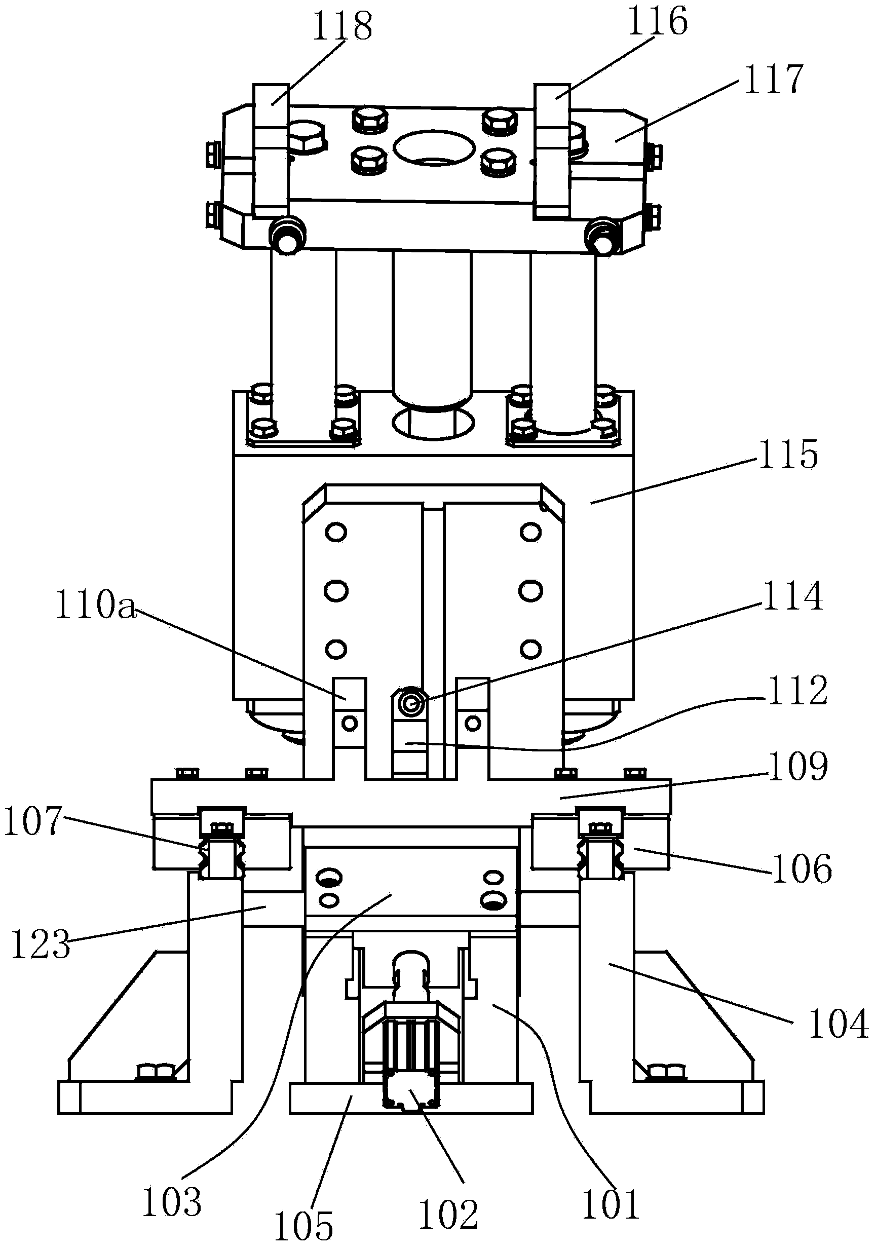
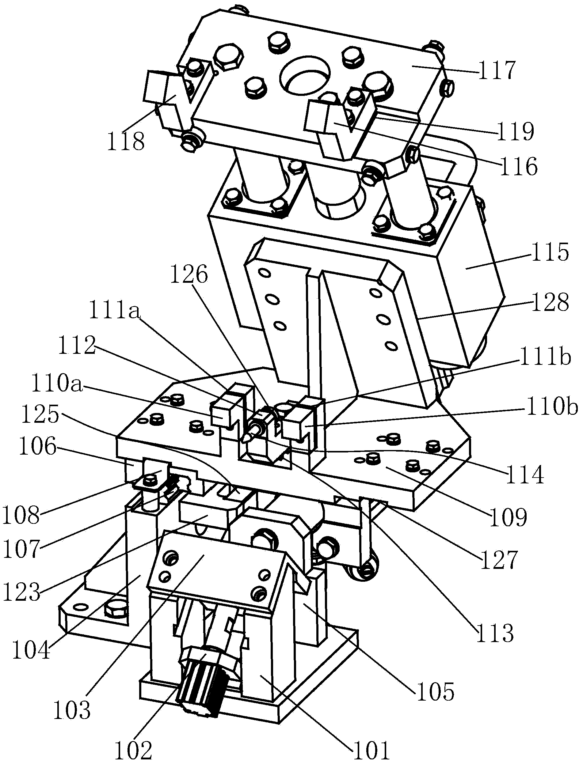
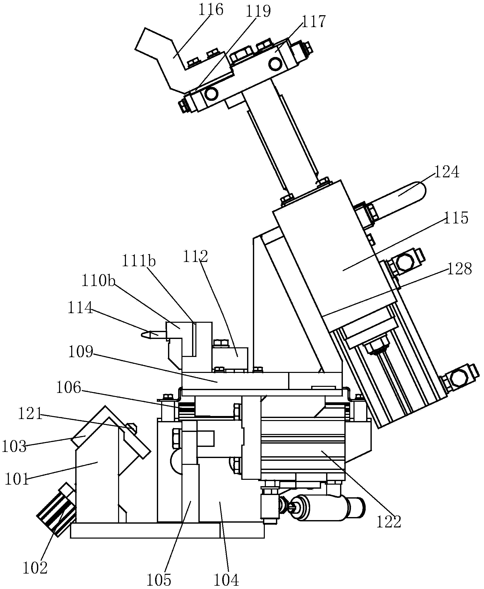
[0023] Such as Figure 1 to Figure 7 As shown, a bracket fixture is installed on the steering column of an automobile instrument panel crossbeam, including a bracket 104; the middle part of the bracket 104 is provided with a lower cylinder 122, and the left and right inner sides of the bracket 104 are provided with a lower pad 123 , and the lower pad 123 is provided with a lower gasket 125, and the upper end faces of the left and right parts of the bracket 104 are provided with a slideway 107; the slideway 107 is covered with a carriage 106; Both are provided with guide piece 108, and the lower plate 109 is fixed on the upper end of the carriage 106, and the guide piece 108 passes through the groove 127 provided on the lower surface of the lower...


PUM


Abstract

The invention relates to a clamp for a steering column upper installation support of a dashboard cross beam. The clamp comprises a bracket, wherein a lower air cylinder is arranged in the middle of the bracket, lower cushion blocks are arranged on the inner sides of the left portion and the right portion of the bracket, lower gaskets are arranged on the lower cushion blocks, and sliding ways are arranged on the upper end faces of the left portion and the right portion of the bracket. Sliding frames are sleeved with the sliding ways, guide pieces are arranged above the sliding frames, lower flat plates are fixed at the upper ends of the sliding frames, and grooves are formed in the guide pieces penetrating through the lower end faces of the lower flat plates. The lower air cylinder is connected with the lower end faces of the lower flat plates, an air cylinder shaft of the lower air cylinder is connected with a front bracket, and a front pushing column is arranged at the upper end of the front bracket. By means of the V-shaped front pushing plate with a concave opening, overcompression of the steering column upper installation support on a front air cylinder with small power is avoided, and pushing effect of the front air cylinder on the steering column upper installation support is ensured. By means of hole positioning nails and positioning nails, the clamp can clamp the steering column upper installation support of the dashboard cross beam accurately.

Description

technical field [0001] The invention relates to the technical field of automobile welding fixtures, in particular to a fixture for installing a bracket on a steering column of an automobile instrument panel beam. Background technique [0002] In recent years, the domestic automobile industry has grown rapidly, and the competition in the automobile market has become increasingly fierce. While vigorously developing new models, various automobile manufacturers have also paid more and more attention to the quality of the complete vehicle. The most important factor affecting the quality of the complete vehicle One of them is the welding jig. In the process of automobile production, basically every new model is put into production, and the corresponding welding jig needs to be invested. According to the current market situation, the period from the development of new models to the promotion of the market requires a short cycle. Therefore, the design of the welding jig , manufactur...

Claims


Application Information

Patent Timeline
Patent Type & Authority Applications(China)
IPC IPC(8): B23K37/04
CPCB23K37/0443
Inventor 钱炳南韦德飞管国凯
Owner ANHUI DACHANG TECH
Learn More