
Welding fixture for automotive dashboard beam assembly

A technology for automobile instrument panel and crossbeam assembly, which is applied in welding equipment, auxiliary welding equipment, welding/cutting auxiliary equipment, etc., and can solve the problems of insufficient positioning and clamping functions, no automatic clamping, and flexible adjustment of clamps, etc.

Active Publication Date: 2014-07-30
ANHUI DACHANG TECH
View PDF5 Cites 10 Cited by
  • Summary
  • Abstract
  • Description
  • Claims
  • Application Information

AI Technical Summary

Problems solved by technology

[0005] The patent No. ZL200920165197.9 discloses a fixture for manufacturing the digital model of the automobile instrument panel beam assembly, which includes a base and a clamping mechanism and a shape-correcting mechanism arranged on the base. The clamping mechanism includes two main The clamping mechanism and the two end clamping mechanisms, the digital model of the instrument panel beam assembly is horizontally arranged on the top of the clamping mechanism along its length direction, by adopting the above structure, the clamping mechanism can control the automobile instrument panel beam assembly However, the positioning and clamping function of the clamping mechanism is insufficient. The cylinder is not used to realize the automatic clamping of the clamp, and no measures are taken to flexibly adjust the clamping and positioning device on the plane or in three dimensions, especially When there is a large misalignment between the fixture and the automobile dashboard beam assembly, the fixture cannot be adjusted flexibly

Method used


Image

  • Welding fixture for automotive dashboard beam assembly
  • Welding fixture for automotive dashboard beam assembly
  • Welding fixture for automotive dashboard beam assembly

Examples


Embodiment Construction

[0039] In order to make the technical means, creative features, goals and effects achieved by the present invention easy to understand, the present invention will be further described below in conjunction with specific illustrations.

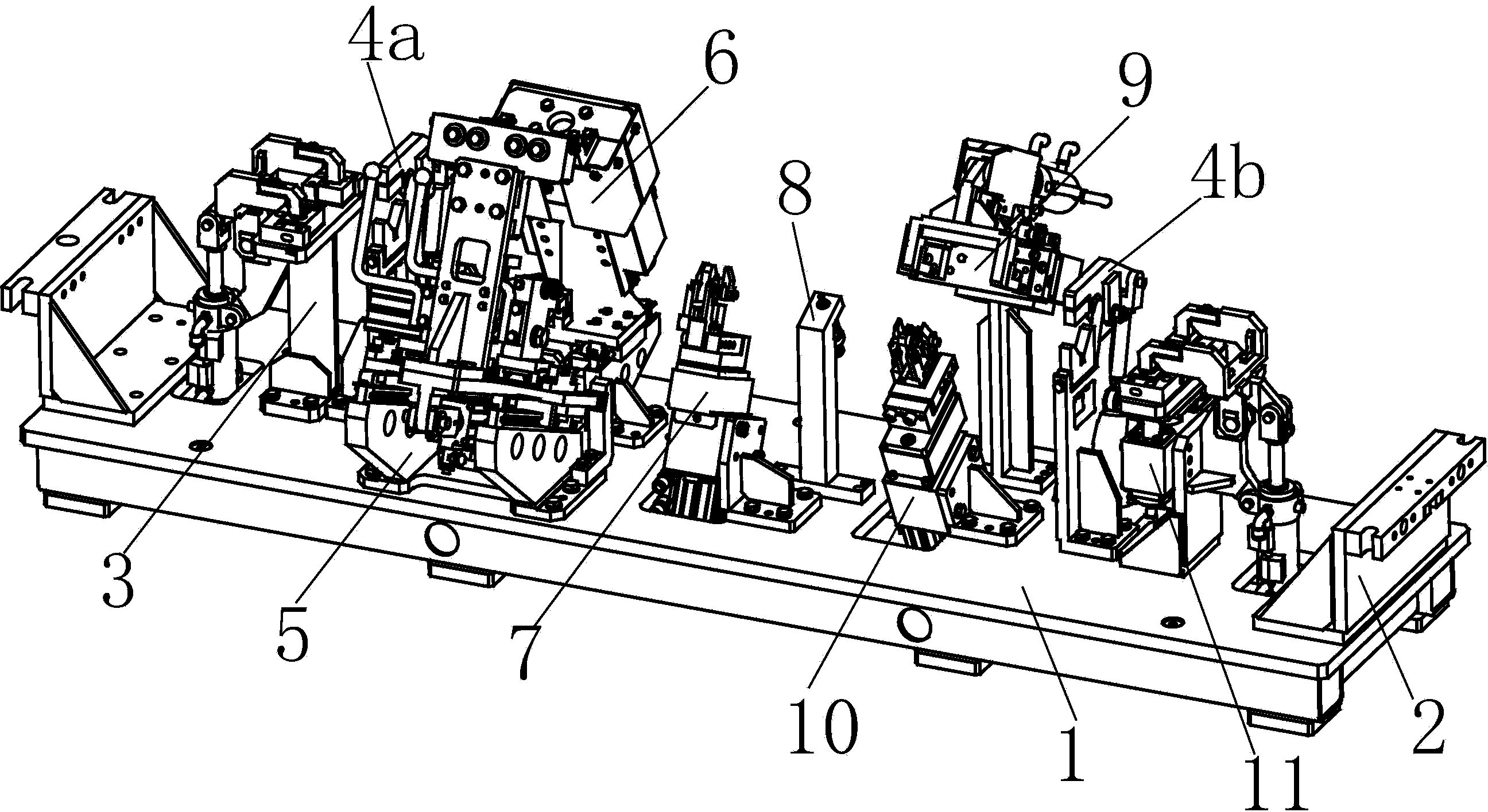
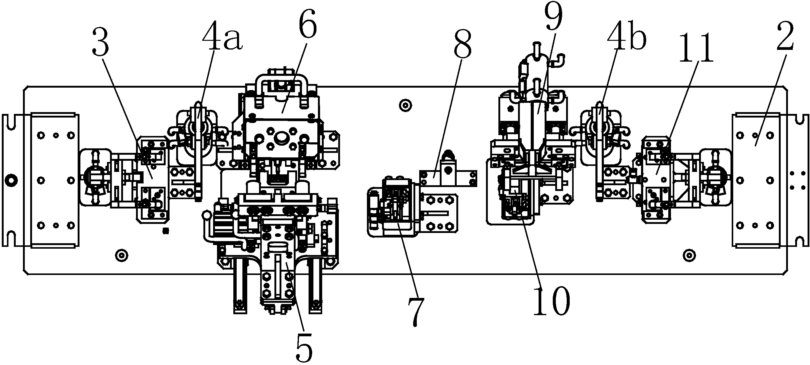
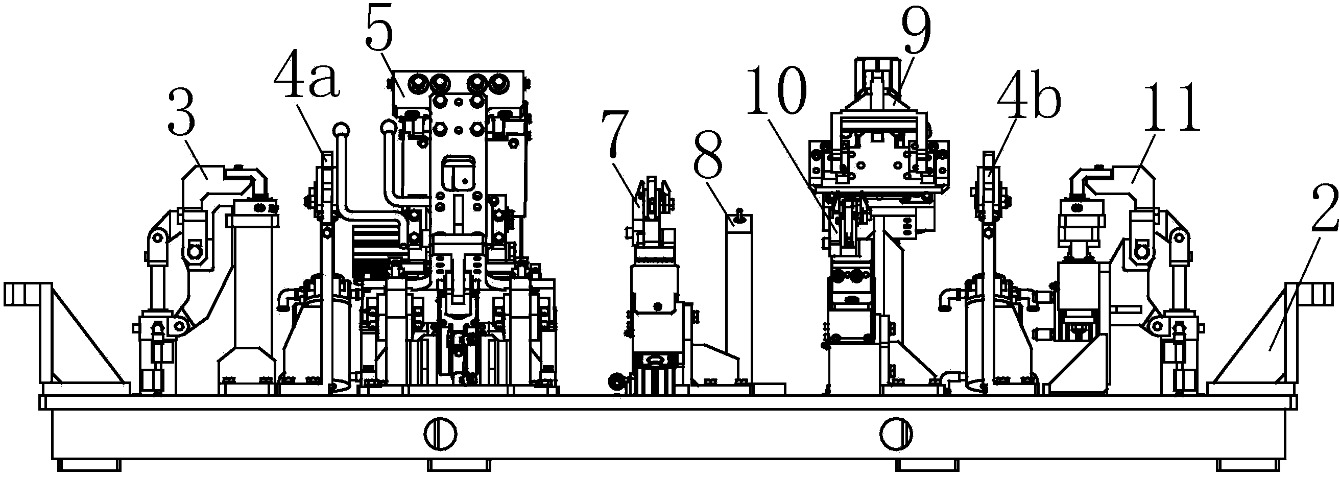
[0040] Such as Figure 1 to Figure 20 As shown, a welding fixture for an automobile instrument panel crossbeam assembly includes a clamping table 1, and a fixing frame 2 is respectively provided at the left and right ends of the mounting table 1. When in use, the fixing frame 2 is connected with a For the motor of the clamping platform 1, the left side of the clamping platform 1 is provided with a beam left side bracket assembly clamping frame 3; the right side of the beam left side bracket assembly clamping frame 3 is provided with a The left crossbeam clamping frame 4a at the left end of the board crossbeam; the right front of the left crossbeam clamping frame 4a is provided with a steering column lower mounting bracket assembly clamping frame...


PUM


Abstract

The invention relates to a welding fixture for an automotive dashboard beam assembly. The welding fixture comprises a clamping table, wherein a beam left-side bracket assembly clamping frame is arranged on the left side of the clamping table; a left beam clamping frame is arranged on the right side of the beam left-side bracket assembly clamping frame; a steering pipe column lower mounting bracket assembly clamping frame is arranged in the right front of the left beam clamping frame; a steering pipe column upper mounting bracket clamping frame is arranged at the right back of the left beam clamping frame; a middle air outlet pipe mounting bracket clamping frame is arranged in the right front of the steering pipe column upper mounting bracket clamping frame; an air outlet positioning frame is arranged at the right back of the middle air outlet pipe mounting bracket clamping frame; a clamping frame of a box body mounting bracket inside a glove box is arranged on the right side of the air outlet positioning frame; a PAB mounting bracket clamping frame is arranged behind the clamping frame of the box body mounting bracket inside a glove box. The welding fixture for the automotive dashboard beam assembly has the advantages of convenience in adjustment, safety and reliability in clamping, accuracy in positioning and the like. A No.3 left push rod and a No. 3 right push rod are convenient for a user to perform manual positioning in a manual reciprocating manner of the No.3 left push rod.

Description

technical field [0001] The invention relates to the technical field of automobile welding fixtures, in particular to a welding fixture for an automobile instrument panel beam assembly. Background technique [0002] Welding fixtures are the main equipment of the automobile body-in-white welding line. Only by mastering the design of the body welding fixtures can we better and faster manufacture welding fixtures that meet the functional requirements and have excellent quality, so that they can play their role in automobile production. Some role, and received good economic benefits. The design of automobile body welding fixture is closely related to the structure and precision of stamping parts and process parts. In order to improve the clamping efficiency of welding fixtures, it is necessary to have a clever, convenient and reliable clamping structure. [0003] Most auto parts are thin plate parts, which are easy to deform during welding. The accuracy of the deformed welded pa...

Claims


Application Information

Patent Timeline
IPC IPC(8): B23K37/04
CPCB23K37/0443B23K37/0461
Inventor 钱炳南王本玉丁铭
Owner ANHUI DACHANG TECH
Learn More