Tire state quantity detecting apparatus and method

Inactive Publication Date: 2005-03-17
TOYOTA JIDOSHA KK
View PDF3 Cites 36 Cited by
  • Summary
  • Abstract
  • Description
  • Claims
  • Application Information

AI Technical Summary

Benefits of technology

[0028] If a plurality of detectors are embedded in the tread part, and are aligned in a direction of circumference of the tire, there is a possibility of coexistence of a detector whose embedment portion in the tread part is in contact with the ground and a detector whose embedment portion is not in contact with the ground. If in such a case, there is a possibility that signals indicating results of detection carried out by those detectors are transmitted together, the reliability regarding the signals transmitte

Problems solved by technology

However, the tire may also be other kind

Method used


Image

  • Tire state quantity detecting apparatus and method
  • Tire state quantity detecting apparatus and method
  • Tire state quantity detecting apparatus and method

Examples


Embodiment Construction

[0045] An exemplary embodiment of the invention will be described hereinafter with reference to the accompanying drawings.

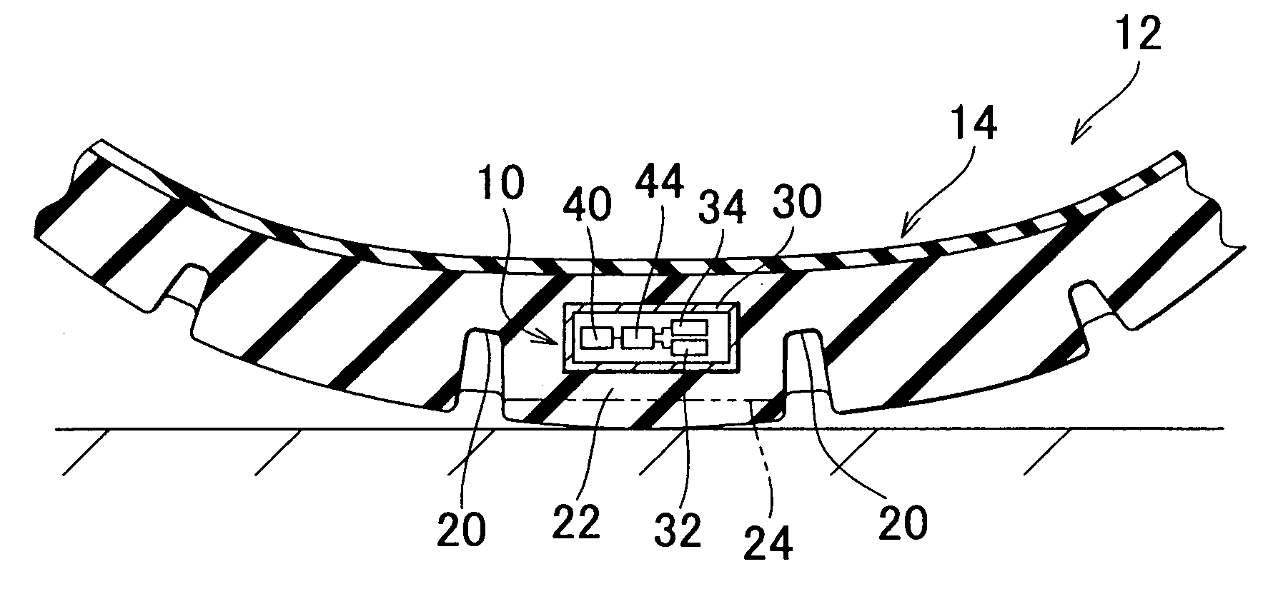
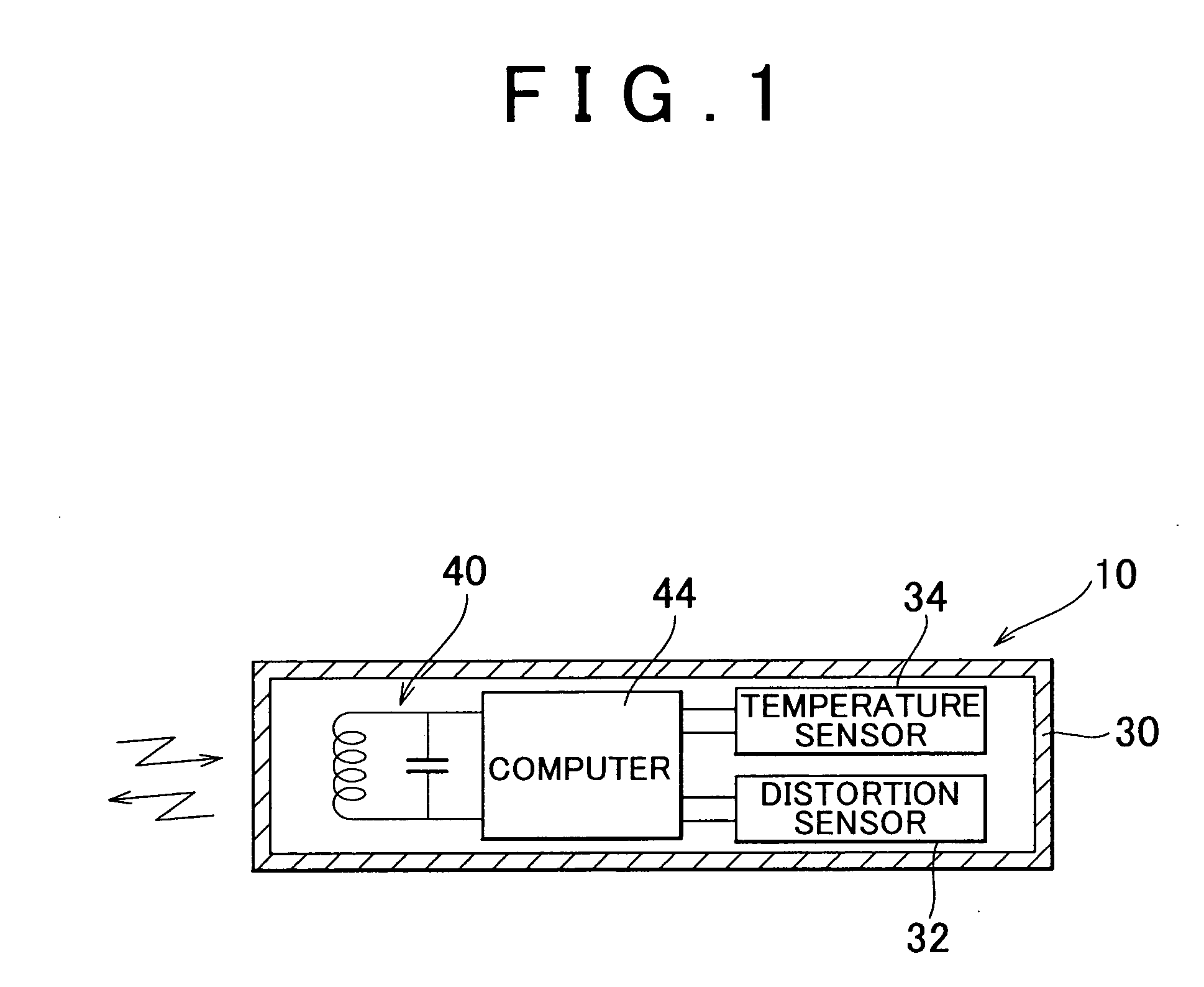
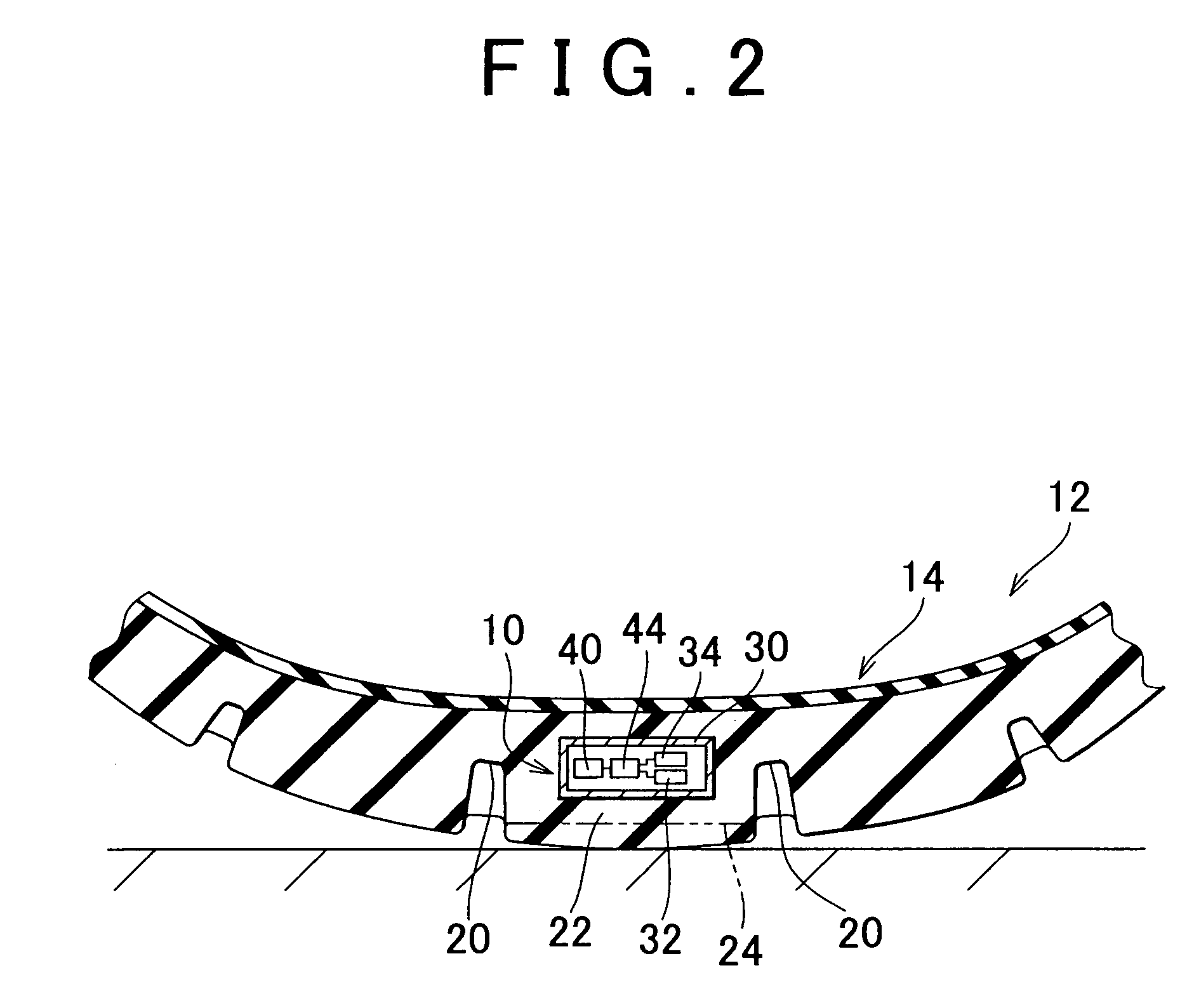
[0046]FIG. 1 shows an enlarged fragmentary sectional view of a tire distortion detecting apparatus 10 in accordance with an embodiment of the invention. The tire distortion detecting apparatus 10, as shown in a front sectional view in FIG. 2, is embedded within a tread part 14 of a tire 12. The tire 12 is attached to a wheel (not shown), and contains air. The tire distortion detecting apparatus 10 is used, on the tire 12-side, to detect a distortion of the tire 12 and, on the vehicle body-side, to estimate a ground contact load of the tire 12 on the basis of the detected distortion.

[0047] As shown in FIG. 2, a surface of the tread part 14 has a plurality of grooves 20, so that a plurality of rubber-made blocks 22 are arranged in a transverse direction with respect to the tire 12. Each block 22 is adjacent to another block 22 across a groove 20.

[0048] In this e...


PUM


Abstract

In a tire state quantity detecting apparatus, a detector that deforms by force exerted from a tire and that outputs a signal corresponding to the quantity of deformation is embedded within the tire. The detector is enclosed in a capsule within the tire, so that the quantity of deformation of the detector is reduced relative to the quantity of deformation of the tire.

Description

[0001] The disclosure of Japanese Patent Application No. 2003-322341 filed on Sep. 16, 2003, including the specification, drawings and abstract is incorporated herein by reference in its entirety. BACKGROUND OF THE INVENTION [0002] 1. Field of Invention [0003] The invention relates to a tire state quantity detecting apparatus and method for detecting a quantity of state of the tire. More particularly, the invention relates to a technology for expanding the range of detection of the tire state quantity. [0004] 2. Description of Related Art [0005] There is a known tire state quantity detecting apparatus that is provided in a tire to detect a quantity of state of the tire as described in Japanese Patent Application Laid-Open Publication No. 2002-36836. [0006] Japanese Patent Application Laid-Open Publication No. 2002-36836 describes a technology in which distortion gages are attached to side surfaces of ribs or blocks provided in a tread part of a tire which contacts the ground, or to ...

Claims


Application Information

Patent Timeline
IPC IPC(8): B60T8/172B60C19/00
CPCB60T8/1725B60C11/243B60C11/246B60T2240/04
Inventor OGAWA, ATSUSHI
Owner TOYOTA JIDOSHA KK
Why Eureka
Try Eureka