Method for scanning LED displayer

A technology of LED display and scanning method, which is applied to static indicators, instruments, etc., can solve the problems of increased hardware cost, inability to guarantee the brightness of LED displays, and backwardness, etc., to achieve the effects of ensuring brightness, guaranteeing display effect, and alleviating the phenomenon of misalignment

Inactive Publication Date: 2014-08-06
ZHANGJIAGANG YANAN AUTOMOBILE ELECTRIC APPLIANCE
View PDF6 Cites 5 Cited by
  • Summary
  • Abstract
  • Description
  • Claims
  • Application Information

AI Technical Summary

Problems solved by technology

Since the scanning time difference between the 1st row to the 8th row and the 9th row to the 16th row is Δt, and only the scanning time difference between the LED row 8 and the LED row 9 is 7Δt, therefore, If the scanning speed is slow, it will cause a sudden change visually, resulting in the feeling that the 8th line lags behind the 9th line display
However, if the scanning speed is accelerated, although the above-mentioned visual mutation will be weakened, the brightness of the LED display cannot be guaranteed.
[0005] In the past, the solution to the above problems was solved by hardware, such as changing 8 scans to 4 scans, 2 scans, or even static scans, but the hardware cost will increase exponentially. times, the static is 2 sweep times

Method used


Image

  • Method for scanning LED displayer
  • Method for scanning LED displayer

Examples


Embodiment 1

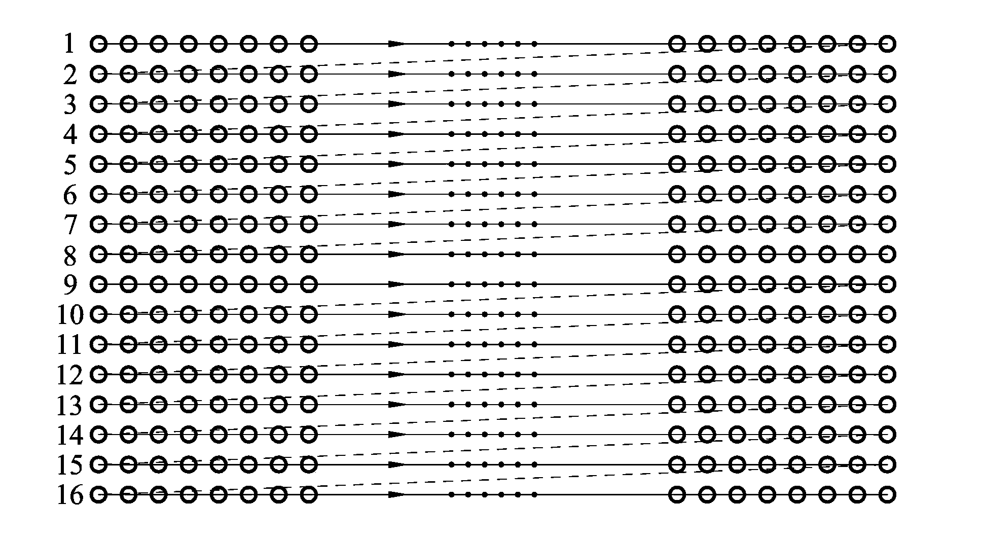
[0015] Embodiment 1: A scanning method of an LED display, as follows: several rows of LEDs in the LED display are equally divided into an upper half and a lower half, and the upper half and the lower half are scanned synchronously using the same scanning order.

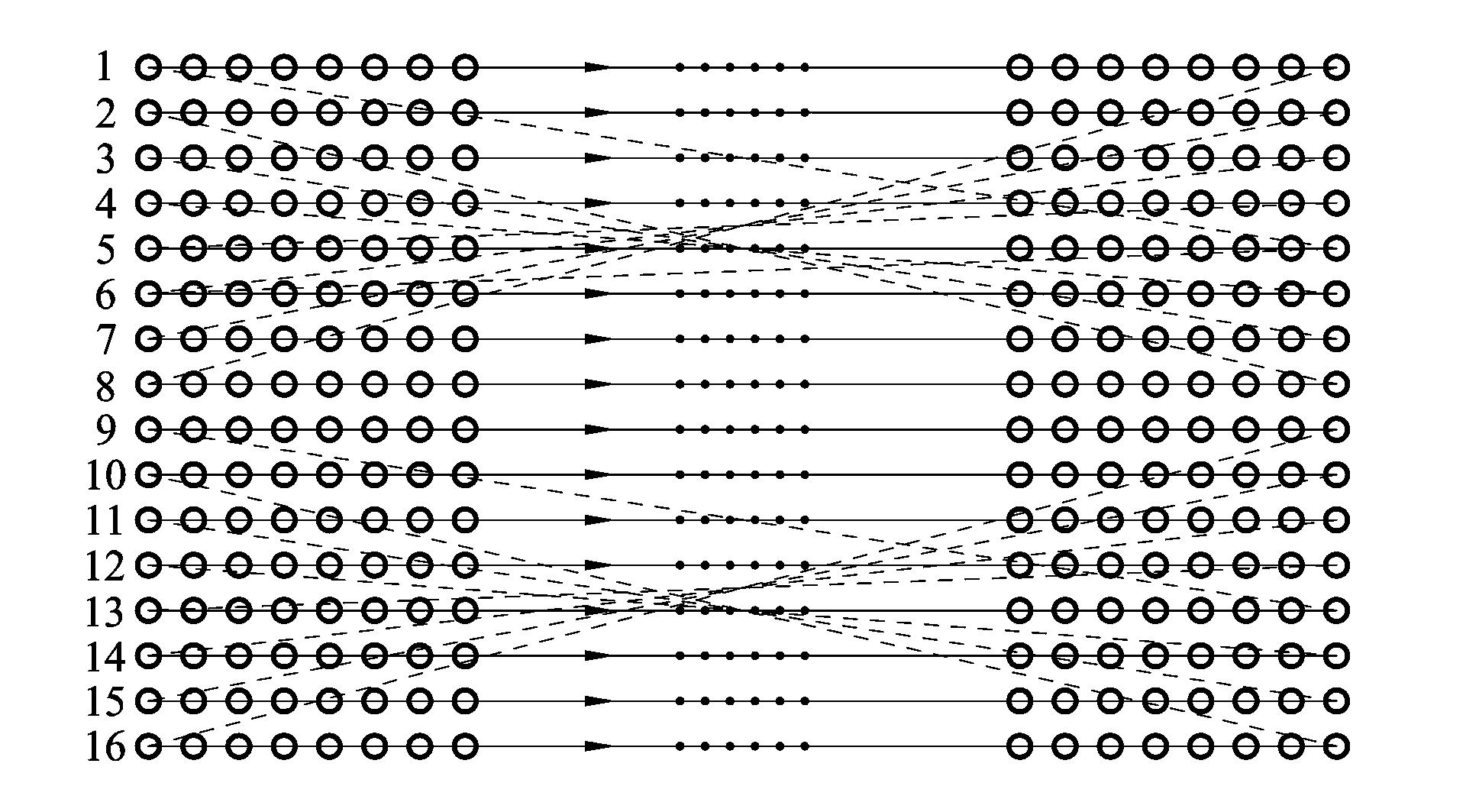
[0016] In the upper or lower half, the specific scanning sequence is: in the upper or lower half, first scan the first row of LEDs, then scan the last row of LEDs, then scan the second row of LEDs below the first row of LEDs, and then scan The penultimate row of LEDs above the last row of LEDs, and so on, gradually scan from the first and last ends of the upper or lower half to the middle, until all rows of LEDs in the upper or lower half are completed once Scan to form a scan cycle. After one scan cycle is completed, the next scan cycle is scanned.

[0017] The preferred scheme of the above-mentioned scanning method is to divide several rows of LEDs needed to display a line of characters or a pattern into upper half...


PUM


Abstract

The invention relates to a method for scanning an LED displayer. The method includes the steps that a plurality of rows of LEDs in the LED displayer are evenly divided into an upper half and a lower half, and the same scanning sequence is adopted in the upper half and the lower half for synchronous scanning. The scanning sequence is as follows: in the upper half or the lower half, the first row of LEDs is scanned, the last row of LEDs is scanned, the second row of LEDs below the first row of LEDs is scanned, the second row of LEDs from the bottom above the last row of LEDs is scanned, the rest can be done in the same manner, scanning is carried out on the upper half or the lower half gradually from the head end and the tail end to the middle until all rows of LEDs of the upper half or the lower half are scanned once, and a scanning cycle is formed. According to the method, under the circumstance that hardware cost is not changed, luminance is guaranteed, meanwhile the phenomenon of error rows is relieved, and therefore the display effect of the LED displayer is guaranteed.

Description

technical field [0001] The invention relates to a scanning method of an LED display. Background technique [0002] The display principle of the LED display is to use the visual residue of the human eye to form an image. Although only one or several rows of LED lights are on at the same time, according to the visual residual effect, people will feel that the LEDs displaying patterns on the screen are all on. [0003] In order to obtain a good visual effect, the image should be refreshed more than 60 times per second, that is, the scanning frequency of 60Hz of a common display. The faster the refresh rate, the better the visuals. However, due to the power-on characteristics of the LED itself, the faster the refresh rate, the lower the brightness of the LED, so there is such a problem that when the refresh rate is low, the image brightness is higher, but due to the visual residual effect, the pattern will go wrong; After increasing the refresh rate, the misalignment phenomen...

Claims


Application Information

Patent Timeline
Patent Type & Authority Applications(China)
IPC IPC(8): G09G3/32
Inventor 陆超
Owner ZHANGJIAGANG YANAN AUTOMOBILE ELECTRIC APPLIANCE
Why Eureka
Try Eureka