Track fixing device

A fixing device and track technology, applied in the direction of track system, transportation and packaging, load hanging components, etc., can solve the problems of troublesome construction, high cost, unreasonable structure, etc., and achieve the effect of solving height problems and compact structure.

Inactive Publication Date: 2014-08-13
安徽唐氏螺纹紧固件有限公司
View PDF1 Cites 0 Cited by
  • Summary
  • Abstract
  • Description
  • Claims
  • Application Information

AI Technical Summary

Problems solved by technology

[0002] To fix the rail on the crane beam, clamps, pressure plates, hook bolts, fasteners, etc. were usually used in the past, but the structure was not reasonable. It is troublesome and affects the strength of the crane beam and rail
In particular, the fixing of the track to the track with horizontal wheels poses a new problem. The invention patent "rail connection device" (ZL200610161330.4) discloses a track fixing device. The fixing device adopts the welding method of the base and the crane beam, and the height It can also meet the needs, but the structure of the fixing parts is more complicated and the cost is higher

Method used


Image

  • Track fixing device
  • Track fixing device
  • Track fixing device

Examples


Embodiment 1

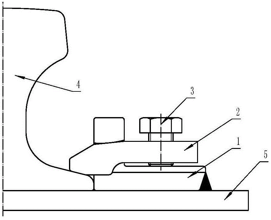
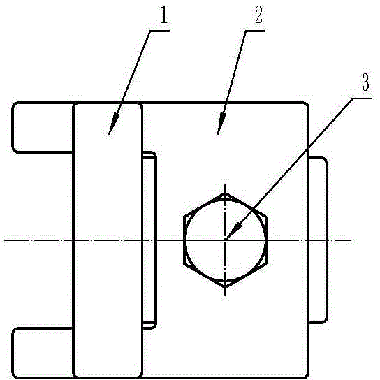
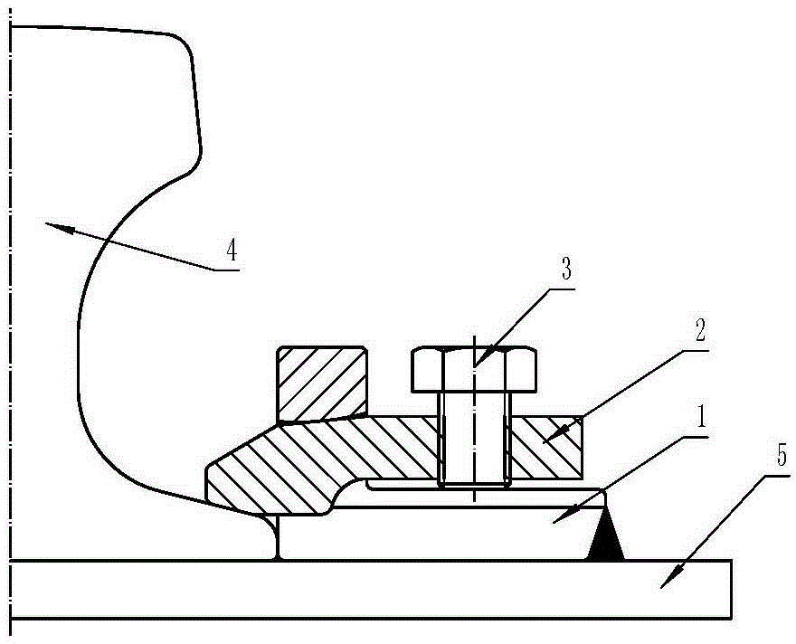
[0010] In Embodiment 1, the base 1 is L-shaped and its lower part is welded on the crane beam 5. There is a crossbeam at the front of the base 1. The front part of the pressure plate 2 is placed under the crossbeam of the base 1 and presses the rail 4. Threaded through hole, the screw 3 passes through the threaded through hole on the pressure plate 2, and the head of the screw 3 is pushed on the base 1 rear part. In this embodiment, the beam of the base 1 stretches to both sides, the pressing plate 2 is U-shaped, and the two ends of the pressing plate 2 protrude from the lower part of the base 1 beam to press the rail 4 .

Embodiment 2

[0011] In the second embodiment, the base 1 is L-shaped and its lower part is welded on the crane beam 7. There is a crossbeam at the front of the base 1. The front part of the pressure plate 2 is placed under the crossbeam of the base 1 and presses the rail 4. Threaded through hole, the screw 3 passes through the threaded through hole on the pressure plate 2, and the head of the screw 3 is pushed on the base 1 rear part. In this embodiment, the crossbeam of the base 1 is arranged in the middle, the pressing plate 2 is T-shaped, and the lower part of the head base 1 crossbeam of the pressing plate 2 stretches out to press the rail 4 . In this embodiment, there are two threaded through holes on the pressing plate 2, and there are also two screws 3.


PUM


Abstract

The invention relates to a track fixing device, and particularly relates to a crane track fixing device. The track fixing device consists of a base, a pressing plate and a screw. The track fixing device is characterized in that the front part of the base is provided with a cross beam; the front part of the pressing plate is arranged at the lower part of the cross beam and presses a steel rail; the rear part of the pressing plate is provided with a treaded through hole; the screw passes through the threaded through hole in the pressing plate; the head part of the screw pushes against the upper surface of the rear part of the base.

Description

technical field [0001] The invention relates to a rail fixing device, in particular to a crane rail fixing device. Background technique [0002] To fix the rail on the crane beam, clamps, pressure plates, hook bolts, fasteners, etc. were usually used in the past, but the structure was not reasonable. It is troublesome and affects the strength of the crane beam and rail. In particular, the fixing of the track to the track with horizontal wheels poses a new problem. The invention patent "rail connection device" (ZL200610161330.4) discloses a track fixing device. The fixing device adopts the welding method of the base and the crane beam, and the height It can also meet the needs, but the structure of the fixing part is relatively complicated, and the cost is also high. Contents of the invention [0003] The object of the present invention is to provide a track fixing device with a more compact structure, which can be used on the driving track with horizontal wheels. [000...

Claims


Application Information

Patent Timeline
Patent Type & Authority Applications(China)
IPC IPC(8): B66C7/08
Inventor 唐宗才
Owner 安徽唐氏螺纹紧固件有限公司
Why Eureka
Try Eureka