

Piece of furniture
A technology for furniture and furniture accessories, which is applied in the field of furniture, and can solve the problems that the upper front panel of the upper drawer should not be set at the same position, etc.
- Summary
- Abstract
- Description
- Claims
- Application Information
AI Technical Summary
Problems solved by technology
Method used
Image

Examples
Embodiment approach
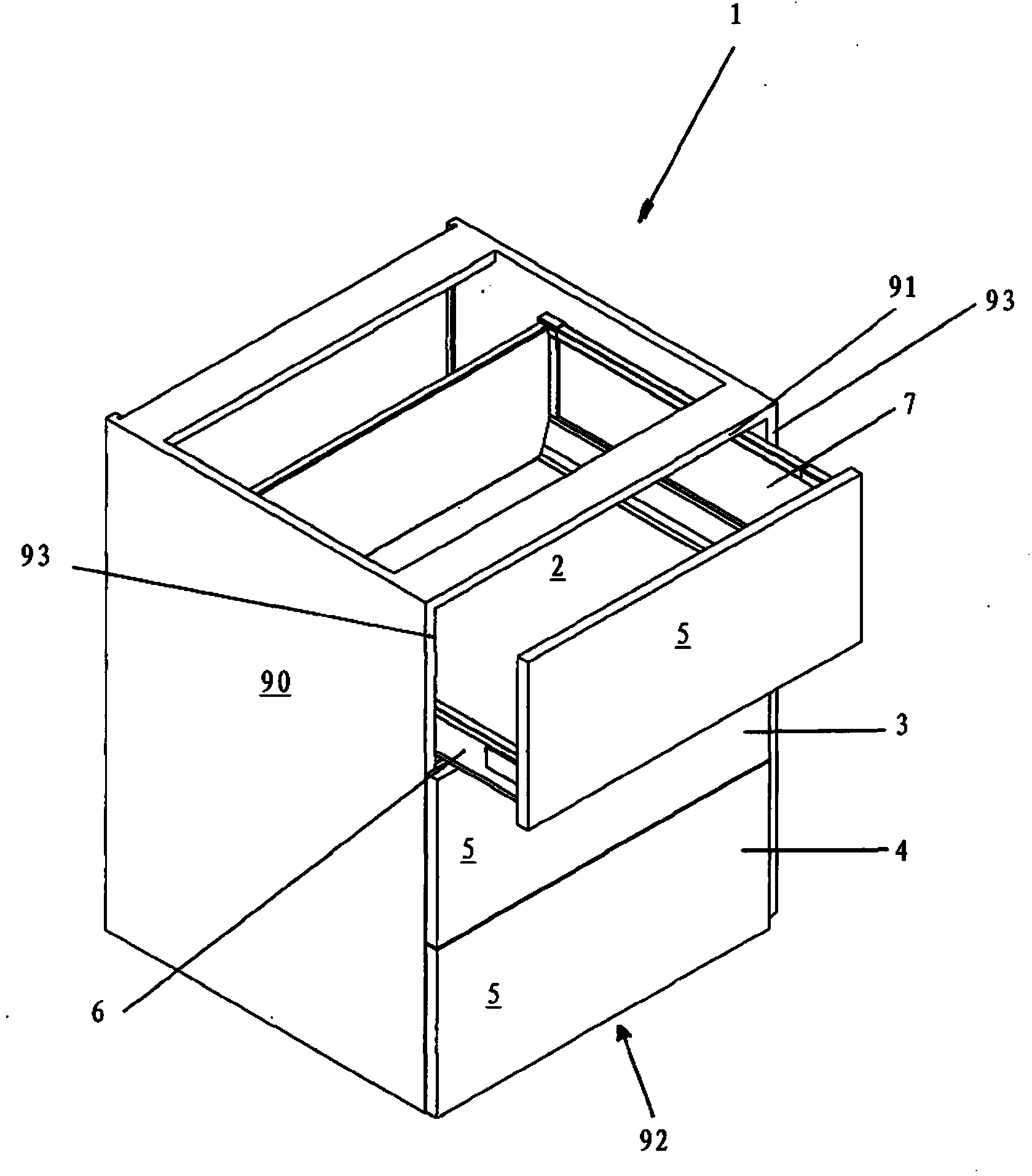
[0029] figure 1 A perspective view of a piece of furniture 1 with three drawers 2 , 3 and 4 is shown. The drawers 2, 3 and 4 have two side walls 6 and 7, respectively. Front panels 5 are respectively fixed on said side walls 6 and 7 of the drawers 2 , 3 and 4 .
[0030] Here, identical front panels 5 are used for all three drawers 2 , 3 and 4 .
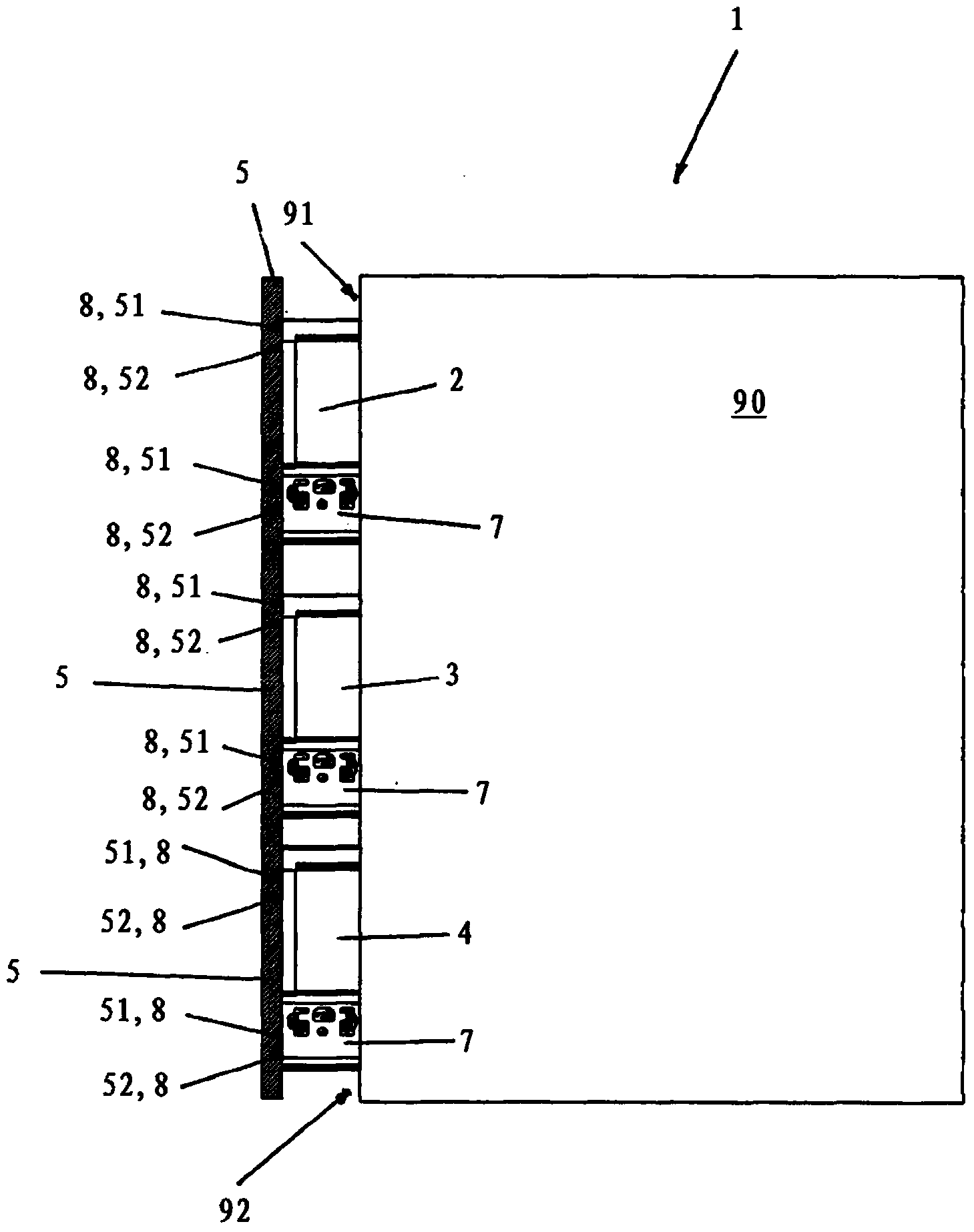
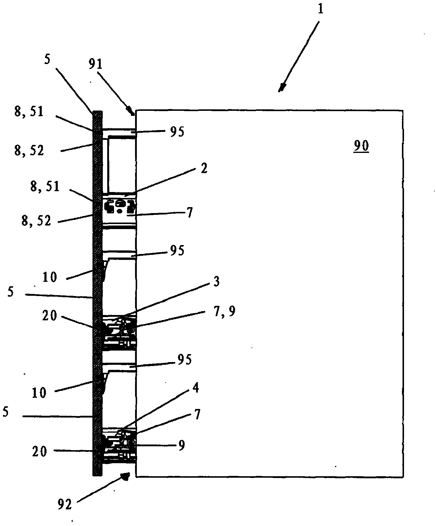
[0031] Said drawers 2 , 3 and 4 are installed in the furniture body 90 of the furniture 1 . In this case, the furniture body part 90 has an end side 91 on its body roof and an end side 93 on its side walls. Below the lowermost drawer 4 there is a body bottom of the body 90 which likewise has an end side 92 .
[0032] In order to achieve an aesthetically pleasing piece of furniture 1 , the front panel 5 of the uppermost drawer 2 covers not only the body side walls 93 but also the body top or the end face 91 of the body top in the closed state.
[0033] The front panel 5 of the middle drawer 3 covers the end side 93 of the body sid...
PUM
 Abstract
Description
Claims
Application Information